A high-pressure single-guided natural gas trap

A technology for natural gas and steam traps, applied in steam traps, mechanical equipment, etc., to reduce costs, improve sealing, and reduce the volume of the shell

Active Publication Date: 2015-11-25
GANSU HONGFENG MASCH CO LTD
View PDF8 Cites 0 Cited by
  • Summary
  • Abstract
  • Description
  • Claims
  • Application Information

AI Technical Summary

Problems solved by technology

[0002] At present, there is a natural gas trap with a nominal pressure of 10.0MPa and a maximum working pressure of 8.0MPa in China, but there is no high-pressure single-conduction natural gas trap with a nominal pressure of 15.0MPa and a maximum working pressure of 10.0MPa.

Method used


Image

  • A high-pressure single-guided natural gas trap
  • A high-pressure single-guided natural gas trap
  • A high-pressure single-guided natural gas trap

Examples


Embodiment Construction

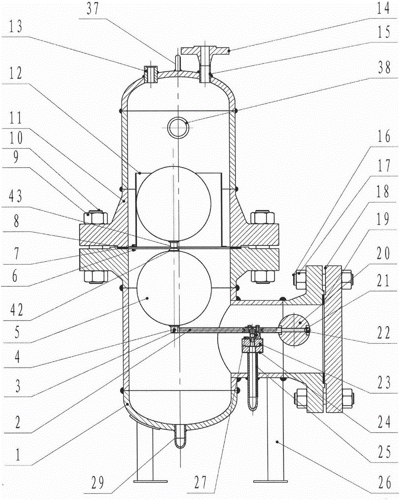
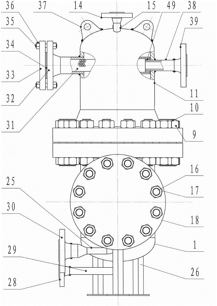
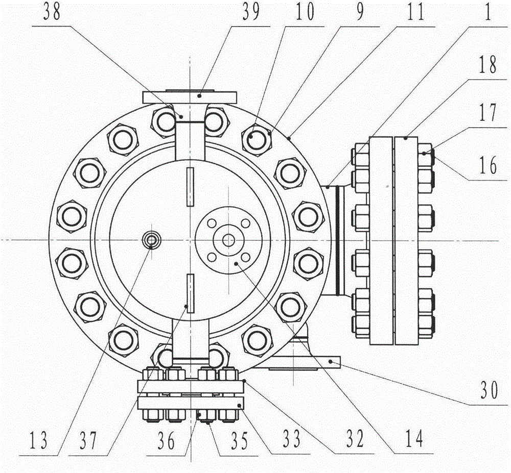
[0033] exist figure 1 , 2 , 3, 4, 6, 7, 8: a fixed gasket 7 is installed between the one-way split lower shell 1 and the upper shell 11, all of which are connected by special double-ended studs I10 and thickened hex nuts 9 fixed. The upper shell 11 and the one-way split lower shell 1 are designed according to PN150, all forged steel parts, and the shell material and strength design conform to "GB150-2011 Pressure Vessel". The right side of the one-way split type lower housing 1 is provided with a split cavity of one-way small cavity, and its function is to reduce volume and cost. A gasket I19 is installed between the split cavity and the blind plate 18, connected by a special double-ended stud II16, and fixed by a hex nut I17. Connect the single guide limit assembly 12 to the fixed sealing gasket 7, respectively connect the three connecting holes I63 with the hexagon head bolt I8, and fix it with the hexagon nut II6. The single guide limit assembly 12 is welded by the guid...


PUM


Abstract

The invention relates to a high-pressure single-guide natural gas trap. The high-pressure single-guide natural gas trap is characterized in that an upper shell 11 is provided with a liquid diversion component 31 penetrating the upper middle of the upper shell, one end of the liquid diversion component 31 penetrates a flange fixing plate 32, a water inlet adapter tube 38 is welded at the other end of a welding connecting plate 33, a single-guide limit component 12 is connected to a fixable gasket 7, and a double-float link component 5 moves in a guide sleeve 46. One end of a long lever 50 is connected with a spool support 51, and the other end of the long lever 51 is connected with double floats 41. One end of a short lever 54 is connected with the spool support 51, and the other end of the short lever 54 is connected with a buoyancy increaser 20. A spool 55 is disposed in the spool support 51. A valve seat 58 is connected to a valve seat fixing plate 57 in a threaded manner. A connecting shaft 60 sequentially penetrates a fixing block I59-1, a connecting block I56-1, a connecting block II56-2 and a fixing block II59-2 to connect the spool support 51 and the valve seat fixing plate 57 together. A valve seat component connecting plate 24 is connected below the valve seat fixing plate 57. An outlet adapter tube 25 is welded at the lower end of a middle hole of the valve seat component connecting plate 24 and penetrates a split cavity wall. The high-pressure single-guide natural gas trap is small in size and low in cost and meets the technical requirement for no leakage.

Description

technical field [0001] The invention relates to a natural gas trap, in particular to a high-pressure single-lead natural gas trap. Background technique [0002] At present, there are natural gas traps with a nominal pressure of 10.0MPa and a maximum working pressure of 8.0MPa in China, but there is no high-pressure single-conduction natural gas trap with a nominal pressure of 15.0MPa and a maximum working pressure of 10.0MPa. Contents of the invention [0003] The technical problem to be solved by the present invention is: under the high working pressure of 10.0Mpa, it can discharge the medium (condensate oil) with a specific gravity of only 0.6-0.65; solve the accuracy of double float seating to meet the parameter requirements of zero leakage; Minimize the external volume and installation space; under severe sand and dust conditions, prolong the service life of the valve seat to meet the discharge of condensed water and condensed oil in domestic high-pressure natural gas ...

Claims


Application Information

Patent Timeline
Patent Type & Authority Patents(China)
IPC IPC(8): F16T1/24F16T1/38
Inventor 魏红徐东升王保军王福来王晓峰郝桂芝
Owner GANSU HONGFENG MASCH CO LTD
Why Eureka
Try Eureka