
Unequal-height variable-speed air distribution particle heat carrier heating furnace for circulating fluidized beds

A circulating fluidized bed and heating furnace technology, which is applied to fluidized bed furnaces, lighting and heating equipment, furnaces, etc., can solve the problems of high energy consumption, low combustion share in the dense phase area, and difficult control, and achieve energy consumption Low, easily controlled effect

Active Publication Date: 2013-07-10
陕西德源建设开发有限公司
View PDF6 Cites 3 Cited by
  • Summary
  • Abstract
  • Description
  • Claims
  • Application Information

AI Technical Summary

Problems solved by technology

[0005] The invention provides a unequal height, variable speed air distribution circulating fluidized bed granular heat carrier heating furnace, which mainly solves the problems of low combustion share, high energy consumption and difficult regulation and control in the dense phase area of ​​the prior art

Method used


Image

  • Unequal-height variable-speed air distribution particle heat carrier heating furnace for circulating fluidized beds

Examples


Embodiment 1

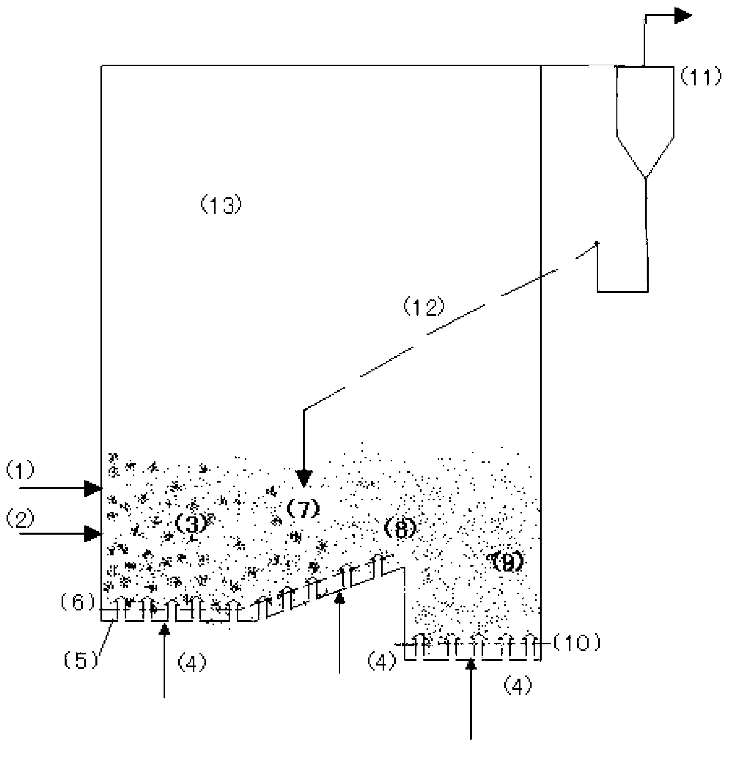
[0020] Such as figure 1 As shown: this air distribution structure divides the fluidized bed dense phase area into three functional areas, according to the flow direction of the particle heat carrier: first, the fuel 1 and the particle heat carrier 2 to be heated are sent to a constant-height, high-speed area 3, where they are burned And the fluidizing air 4 is supplied from the bed bottom hood 5, the hood holes are at the same elevation 6, and the superficial gas velocity is 0.7-1.2m / s, which is suitable for the combustion and good fluidization of large particle fuel; It is a zone of unequal height and low velocity 7. Along the direction of material flow, the elevation of the air supply point rises by 3-10°8, and the superficial air velocity is 0.15-0.3m / s. Many large particles will be brought into this area. In the first area, it is the inclined air distribution that makes the large particles flow back to the high-speed area, forming a circulation of large particles without s...

Embodiment 2

[0022] The third zone and the first and second zones in the first embodiment are turned and arranged in the opposite direction, and the whole bed is U-shaped. This structure avoids the problem of a long bed shape in the first embodiment, and the other parameters are the same as in the first embodiment.

[0023] For example, the furnace type of the present invention can be used to incinerate and dry sludge, and the heated particle heat carrier is used for drying wet sludge. Sludge has the characteristics of dispersed particle size, more fine particles, and high volatile content of combustible base. It is very important to ensure a high combustion share in the dense phase zone. This type of furnace can ensure good fluidization of coarse particle sludge and ensure that fine materials stay in the dense phase area for a long time, and the combustion share in the dense phase area is very high.

[0024] Another example is that the furnace type of the present invention can be used for...


PUM


Abstract

The invention provides an unequal-height variable-speed air distribution particle heat carrier heating furnace for circulating fluidized beds and mainly solves the problems of low burning shares, high energy consumption and difficulty in regulation in dense-phase zones in the prior art. The unequal-height variable-speed air distribution particle heat carrier heating furnace for circulating fluidized beds comprise fluidized bed dense-phase zones arranged in the furnace body. An equal-height high-speed zone, an unequal-height low-speed zone and an equal-height low-speed zone are sequentially arranged in the fluidized bed dense-phase zones from a material inlet to a material outlet. By the aid of the special air distribution structure, particle heat carriers are completed in a group of fluidized bed dense-phase zones which are communicated to each other and different in functions from entering to discharging, no high height difference is caused, and the unequal-height variable-speed air distribution particle heat carrier heating furnace is low in energy consumption and easy to control.

Description

technical field [0001] The invention relates to a circulating fluidized bed furnace for heating granular heat carriers in a dense phase area, in particular to a circulating fluidized bed furnace for heating granular heat carriers in a dense phase area with unequal heights and variable speed air distribution. Background technique [0002] The high-temperature granular heat carrier is used in the processes of material drying, heating or low-temperature carbonization of coal. The circulating fluidized bed furnace can be used to burn fuel to heat the granular heat carrier. The J-shaped valve leads out, and the particle size is mainly <100μ; it can also be drawn out from the dense phase area, and the particle size is mainly >200μ. [0003] Based on the above-mentioned particle size derived from the dense-phase area is mainly >200μ, it can be seen that the heating furnace that extracts the particle heat carrier from the dense-phase area should at least ensure a higher com...

Claims


Application Information

Patent Timeline
IPC IPC(8): F27B15/10
Inventor 霍奇志张诚
Owner 陕西德源建设开发有限公司
Learn More