
Novel reflection type reciprocity optical voltage mutual inductor and optical path design method thereof

An optical voltage and design method technology, applied in the direction of voltage/current isolation, etc., can solve the problems of poor measurement accuracy, stability and environmental adaptability of transformers, difficult influence, and difficulty in accurate measurement and accurate quantification of birefringence errors. Achieve the effect of realizing optical path reciprocity, improving measurement accuracy, and improving measurement accuracy and stability

Active Publication Date: 2013-07-10
安徽华驰动能科技有限公司
View PDF3 Cites 12 Cited by
  • Summary
  • Abstract
  • Description
  • Claims
  • Application Information

AI Technical Summary

Problems solved by technology

The sensor head as the signal sensing unit is a non-reciprocal part of the optical path, so the crystal itself produced by the electro-optic crystal manufacturing process and the additional birefringence errors introduced by factors such as temperature and stress changes will lead to the measurement accuracy, stability and reliability of the transformer. Important Factors of Poor Environmental Adaptability
In addition, the above-mentioned additional birefringence error is extremely difficult to accurately measure and quantify, so it is difficult to obtain a clear numerical expression for software compensation through theoretical analysis.

Method used


Image

  • Novel reflection type reciprocity optical voltage mutual inductor and optical path design method thereof
  • Novel reflection type reciprocity optical voltage mutual inductor and optical path design method thereof
  • Novel reflection type reciprocity optical voltage mutual inductor and optical path design method thereof

Examples


Embodiment Construction

[0025] The present invention will be described in detail below in conjunction with the accompanying drawings and embodiments.

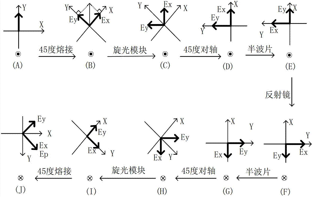
[0026] The present invention proposes a reflective reciprocity optical voltage transformer based on the Pockels effect and its design method. The optical path of the optical voltage transformer obtained by the design method can not only eliminate the defects of the electro-optic crystal itself, but also the environmental temperature and stress changes. The additional birefringence error introduced by other factors, and makes the entire optical voltage transformer optical path immune to the surrounding environment interference, and at the same time, the linear electro-optical delay phase introduced by the voltage to be measured is doubled, thereby improving the system measurement accuracy, stability, and anti-interference ability and environmental adaptability. The optical path design method is:

[0027] Such as Figure 5 , the polarized light genera...


PUM


Abstract

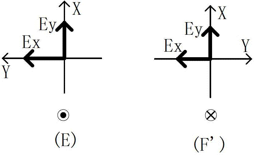
The invention discloses a novel reflection type reciprocity optical voltage mutual inductor based on the Pockels effect and an optical path design method of the reflection type reciprocity optical voltage mutual inductor, and belongs to the technical field of optical voltage mutual inductors. Optical path reciprocity between a polarized light generation module and an optical rotation module is formed through the optical rotation action of the optical rotation module on two orthogonal line polarized lights which pass the optical rotation module for twice in a positive-and-negative mode, and immunity for interference of popularization-maintaining delaying optical cable surrounding environment is strengthened. The two orthogonal line polarized lights are interchanged in mode through a half wave plate, optical path reciprocity of a sensing module is achieved, additional double-refraction error due to electro-optical crystal individual defects and factors such as temperature change and stress change is eliminated, and a reciprocity matched reflector of a sensing module optical path enables a linear electro-optical delay phase introduced by voltage to be tested to be double. According to the novel reflection type reciprocity optical voltage mutual inductor based on the Pockels effect, environment interference resistant capacity and environment adaptive capacity are improved and measuring accuracy and stability of the system are improved.

Description

technical field [0001] The invention belongs to the technical field of optical voltage transformers, and relates to a novel reflective reciprocity optical voltage transformer based on Pockels effect and a design method of reflective reciprocity optical path. Background technique [0002] With the development of power systems towards high voltage, large capacitance, and digitization, higher performance requirements are put forward for power measurement systems. As a voltage measurement device, traditional voltage transformers are increasingly unsuitable for the development of power systems due to their inherent defects, thus promoting the emergence and development of optical voltage transformers. The optical voltage transformer is a voltage measurement device that senses the voltage information to be measured by the change of the optical signal. Optical voltage transformers have been extensively researched and developed rapidly due to a series of advantages such as small siz...

Claims


Application Information

Patent Timeline
Patent Type & Authority Applications(China)
IPC IPC(8): G01R15/24
Inventor 李慧李立京张文慧潘锐许文渊
Owner 安徽华驰动能科技有限公司
Learn More