Middle-infrared band athermal optical compensation continuous zooming optical system

An optical system and optical compensation technology, applied in optics, optical elements, diffraction gratings, etc., can solve the problems of not realizing optical passive athermalization function, not considering optical passive athermalization, not realizing athermal design, etc. Achieve excellent optical performance, compact structure, good cold reflection effect

Active Publication Date: 2013-07-10
SOUTH WEST INST OF TECHN PHYSICS
View PDF8 Cites 16 Cited by
  • Summary
  • Abstract
  • Description
  • Claims
  • Application Information

AI Technical Summary

Problems solved by technology

However, due to the constant spacing of the zoom lens group, it is impossible to compensate for problems such as aberration balance in the zooming process, and the focal length change process is discrete, and the zoom lens group can only move to a few positions to form a clear image, and cannot be like a mechanically compensated lens. The zoom system can achieve continuous zoom through the movement of the zoom lens group and the compensation group on the axis at different rates and directions
[0004] U.S. Patent US3294471 discloses an optical lens based on the principle of optical compensation. This optical lens realizes continuous zooming through an appropriate distance between the zoom lens groups, but its designed range of use is only in the visible light band, without considering the optical passive athermalization difference. In the use of different temperature environments, it is necessary to manually or mechanicall

Method used


Image

  • Middle-infrared band athermal optical compensation continuous zooming optical system
  • Middle-infrared band athermal optical compensation continuous zooming optical system
  • Middle-infrared band athermal optical compensation continuous zooming optical system

Examples


Embodiment Construction

[0025] In order to further clearly illustrate the present invention, specific embodiments will be provided below and combined with the accompanying drawings to describe the technical solution, but they should not be construed as limiting the present invention.

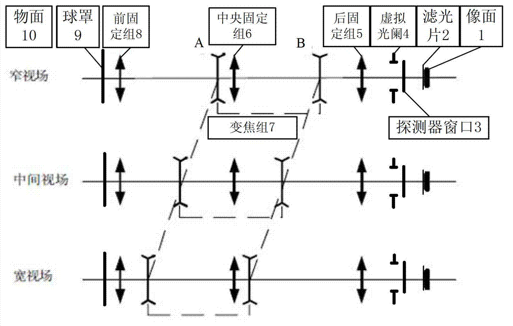
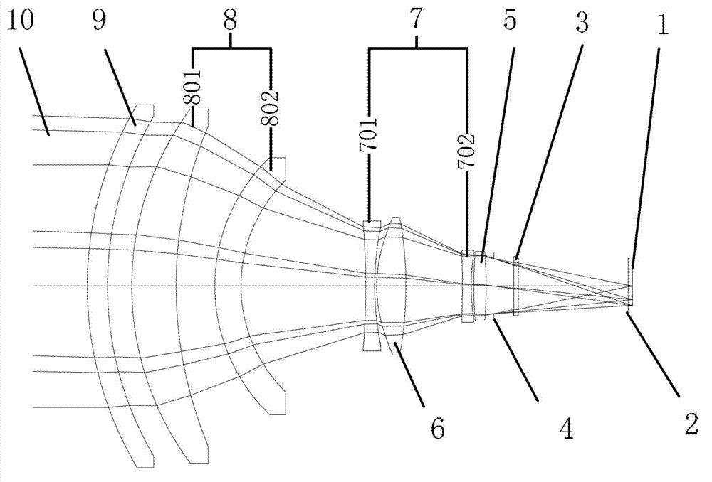
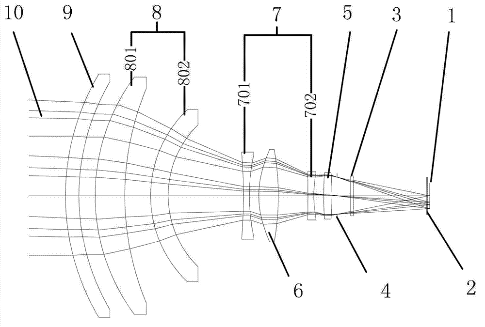
[0026] figure 1 The mid-infrared band athermal difference optical compensation continuous zoom optical system and the principle of optical compensation zoom are described. The fixed dome cover, the front fixed lens group, the zoom lens group and the rear fixed lens group are arranged sequentially from the object plane to the focal plane. A zinc selenide positive lens is arranged between two negative lenses of the zoom lens group as a middle fixed lens group, and a rear fixed group is a positive lens made of silicon material. The zoom lens group forms a complete imaging system together with the front fixed lens group, the middle fixed lens group and the rear fixed lens group. The total length of the optical system rema...


PUM


Abstract

The invention provides a middle-infrared band athermal optical compensation continuous zooming optical system, and aims at providing the middle-infrared band zooming optical structure which can achieve the continuous change, from 60mm to 150mm, of an optical passive thermal difference and a focal distance in -45 DEG C to 60 DEG C. The system is achieved through the technical scheme including that in a lens cone optical system, a dome cover (9) which is made of hot-pressing magnesium fluoride (MgF2) is arranged between an object plane (10) and a front fixed lens group (8), a middle fixed lens group (6) is arranged between a concave lens (701) and a concave lens (702) of a zooming lens group (7), the space between the concave lens (701) and the concave lens (702) remains unchanged, a motor which is fixedly connected on a lens cone serves as a driving source of the two lens concave lenses, a gear-guide rail mechanism drives the zooming lens group (7) to move in an optical axis direction of the optical system in a back-and-forth and linear mode, continuous zooming is achieved through moving in the optical axis direction in a back-and-forth mode, and the zooming lens group (7), the front fixed lens group (8), the middle fixed lens group (6) and a rear fixed lens group (5) collectively form a complete imaging system.

Description

technical field [0001] The invention relates to an adiabatic continuous zoom optical system mainly used in the mid-wave infrared band. Specifically, the present invention relates to an optical system using optically compensated continuous zoom and having an optically passive athermalization function. Background technique [0002] When the optical instrument is used in a large temperature range, the thermal expansion and contraction of the lens barrel material, the optical material, and the temperature refractive index coefficient of the optical material will change the focal power of the lens, resulting in defocusing phenomenon, while the heat of the lens barrel material Expansion and contraction will also cause the optical system to defocus and degrade the image quality. In order to reduce the impact of temperature changes on the imaging quality of the infrared optical system, an athermal design, or athermal difference design, is required, that is, through certain mechanic...

Claims


Application Information

Patent Timeline
IPC IPC(8): G02B15/17G02B15/20
Inventor 邓键龙波钟小兵陈代中汤磊童静张小川
Owner SOUTH WEST INST OF TECHN PHYSICS
Why Eureka
Try Eureka