Mark period level light intensity accumulation based method for determining and searching alignment mark and alignment system
A technology for aligning marks and markings, which is applied in the directions of optics, microlithography exposure equipment, and photolithography on patterned surfaces. Machine productivity and other issues
- Summary
- Abstract
- Description
- Claims
- Application Information
AI Technical Summary
Problems solved by technology
Method used
Image

Examples
Embodiment 1
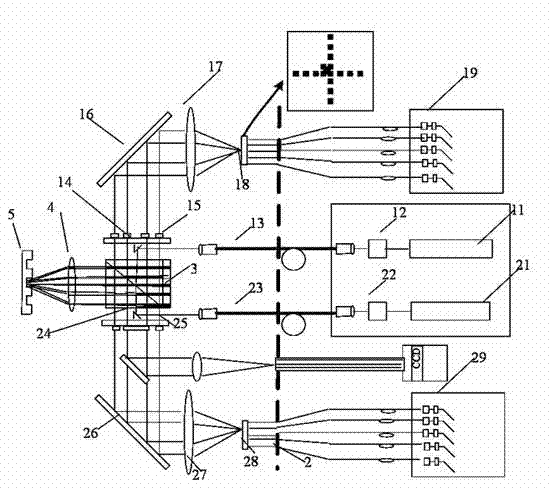
[0060] figure 1 Shown is a schematic diagram of a conventional dual-light source multi-stage alignment system.
[0061] Such as figure 1 As shown, the dual light source multi-level alignment system includes light source modules 11, 21, reference grating 2, optical fibers 13, 23, prisms 14, 24, polarizer 3, objective lens 4, mark 5, and order wedge 15, 25, Mirrors 16, 26, objective lenses 17, 27, image planes 18, 28, and detectors 19, 29.
[0062] The specific working principle of the dual-light source multi-stage alignment system is common knowledge for people with general knowledge in the field, and will not be repeated here.
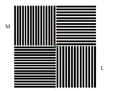
[0063] figure 2 Shown is the composition form of the alignment mark. After the mark is irradiated by the alignment system, the reflection information of each level of light is obtained.
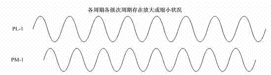
[0064] image 3 Shown is a schematic diagram of the waveform collected for light intensity superposition after this type of mark is illuminated.
[0065] In this embodime...
Embodiment 2
[0079] figure 1 Shown is a schematic diagram of a conventional dual-light source multi-stage alignment system.
[0080] Such as figure 1 As shown, the dual light source multi-level alignment system includes light source modules 11, 21, reference grating 2, optical fibers 13, 23, prisms 14, 24, polarizer 3, objective lens 4, mark 5, and order wedge 15, 25, Mirrors 16, 26, objective lenses 17, 27, image planes 18, 28, and detectors 19, 29.
[0081] The specific working principle of the dual-light source multi-stage alignment system is common knowledge for people with general knowledge in the field, and will not be repeated here.
[0082] figure 2 Shown is the composition form of the alignment mark. After the mark is irradiated by the alignment system, the reflection information of each level of light is obtained.
[0083] image 3 Shown is a schematic diagram of the waveform collected for light intensity superposition after this type of mark is illuminated.
[0084] In this embodime...
Embodiment 3
[0100] figure 1 Shown is a schematic diagram of a conventional dual-light source multi-stage alignment system.
[0101] Such as figure 1 As shown, the dual-light source multi-stage alignment system includes light source modules 11, 12, reference grating 2, optical fibers 13, 23, prisms 14, 24, polarizer 3, objective lens 4, mark 5, and order wedge 15, 25, Mirrors 16, 26, objective lenses 17, 27, image planes 18, 28, and detectors 19, 29.
[0102] The specific working principle of the dual-light source multi-stage alignment system is common knowledge for people with general knowledge in the field, and will not be repeated here.
[0103] figure 2 Shown is the composition form of the alignment mark. After the mark is irradiated, the alignment system obtains the reflection information of each level of light.
[0104] image 3 Shown is a schematic diagram of the waveform collected for light intensity superposition after this type of mark is illuminated.
[0105] In this embodiment, a r...
PUM
 Abstract
Description
Claims
Application Information
 - R&D
- Intellectual Property
- Life Sciences
- Materials
- Tech Scout
- Unparalleled Data Quality
- Higher Quality Content
- 60% Fewer Hallucinations
Browse by: Latest US Patents, China's latest patents, Technical Efficacy Thesaurus, Application Domain, Technology Topic, Popular Technical Reports.
© 2025 PatSnap. All rights reserved.Legal|Privacy policy|Modern Slavery Act Transparency Statement|Sitemap|About US| Contact US: help@patsnap.com