
Ultrasonic cleaning power system

A technology of power supply system and ultrasonic cleaning, applied to electrical components, output power conversion devices, AC power input to AC power output, etc., can solve problems such as power grid interference and frequency drift, meet miniaturization requirements, and improve competition Force, the effect of simplifying the circuit structure

Inactive Publication Date: 2013-07-10
TRANS POTENT MECHATRONICS SHENZHEN
View PDF3 Cites 11 Cited by
  • Summary
  • Abstract
  • Description
  • Claims
  • Application Information

AI Technical Summary

Problems solved by technology

[0005] In view of the shortcomings of the above-mentioned prior art, the purpose of the present invention is to provide an ultrasonic cleaning power supply system to solve the problems of frequency drift and grid interference in the prior art when adjusting the power of the ultrasonic transducer

Method used


Image

  • Ultrasonic cleaning power system
  • Ultrasonic cleaning power system
  • Ultrasonic cleaning power system

Examples


Embodiment Construction

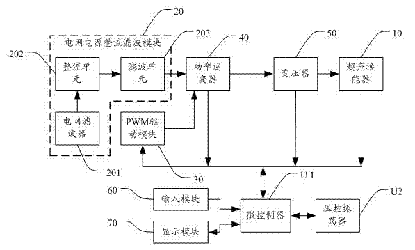
[0037] The present invention provides an ultrasonic cleaning power supply system. In order to make the purpose, technical solution and effect of the present invention more clear and definite, the present invention will be further described in detail below with reference to the accompanying drawings and examples. It should be understood that the specific embodiments described here are only used to explain the present invention, not to limit the present invention.

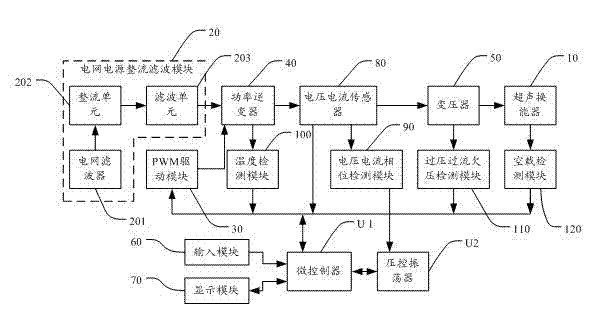
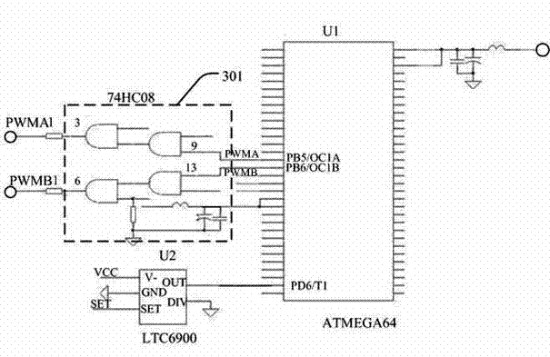
[0038] The ultrasonic cleaning power supply system provided by the present invention is used to control the output power of the ultrasonic transducer 10, please refer to figure 1 , which is a structural block diagram of the first preferred embodiment of the ultrasonic cleaning power supply system of the present invention. Such as figure 1 As shown, the ultrasonic cleaning power system includes a grid power rectification and filtering module 20 , a voltage-controlled oscillator U2 , a microcontroller U1 , a PWM drive...


PUM


Abstract

The invention discloses an ultrasonic cleaning power system which is used for controlling output power of an ultrasonic transducer. The ultrasonic cleaning power system comprises a network source rectifier filter module, a voltage-controlled oscillator, a microcontroller, a PWM driving module, a power inverter and a transformer, wherein the network source rectifier filter module is connected with the power inverter, the microcontroller is connected with the power inverter through the PWM driving module, the power inverter is connected with the ultrasonic transducer through the transformer, and the voltage-controlled oscillator is connected with the microcontroller. According to the ultrasonic cleaning power system, ultrasonic frequency of the ultrasonic cleaning power system is directly output through the microcontroller, the phenomenon that an external voltage-controlled oscillator directly outputs the ultrasonic frequency to cause frequency variations in the prior art is avoided, meanwhile, power regulation of the ultrasonic transducer is directly completed internally through the microcontroller, and a regulating circuit is not needed additionally. The circuit structure is simplified, miniaturization requirements of electronic products are met, and competitiveness of the products on the market is improved.

Description

technical field [0001] The invention relates to the technical field of ultrasonic cleaning, in particular to an ultrasonic cleaning power supply system. Background technique [0002] The frequency of the existing ultrasonic cleaning power supply system mainly controls the power of the ultrasonic transducer through the frequency signal generated by the external voltage-controlled oscillator or the output frequency signal of the microprocessor analog oscillator. When working, the power adjustment generally adopts gap work, Thyristor voltage regulation, changing PWM (Pulse Width Modulation, pulse width modulation) duty cycle and other methods. [0003] However, the frequency generated by the voltage-controlled oscillator is prone to frequency drift, and the method of simply using the microprocessor to simulate the oscillator output frequency signal has the problem of difficult signal processing, such as changing the duty cycle of the PWM signal. Circuit to achieve; power adjus...

Claims


Application Information

Patent Timeline
Patent Type & Authority Applications(China)
IPC IPC(8): H02M5/456
Inventor 陈嵘苏日庆李正中刘力
Owner TRANS POTENT MECHATRONICS SHENZHEN
Learn More