Position observation device and method for rotor of built-in permanent magnetic synchronous motor based on adaptive filtering

A permanent magnet synchronous motor and adaptive filtering technology, applied in the direction of controlling electromechanical transmission devices, electronic commutators, and controlling generators, etc., can solve problems such as the 6th harmonic pulsation observation error, and achieve improved control performance and satisfactory control. The effect of performance, signal processing method is simple and easy to implement

Active Publication Date: 2013-07-10
哈工科讯(沈阳)智能工业技术有限公司
View PDF2 Cites 40 Cited by
  • Summary
  • Abstract
  • Description
  • Claims
  • Application Information

AI Technical Summary

Problems solved by technology

[0005] The purpose of the present invention is to solve the problem that the observation value of the rotor position angle obtained by the existing model method contains the observation error of the 6th harmonic wave, and proposes a built-in permanent magnet synchronous motor rotor position observation device and observation method based on adaptive filtering

Method used


Image

  • Position observation device and method for rotor of built-in permanent magnetic synchronous motor based on adaptive filtering
  • Position observation device and method for rotor of built-in permanent magnetic synchronous motor based on adaptive filtering
  • Position observation device and method for rotor of built-in permanent magnetic synchronous motor based on adaptive filtering

Examples


specific Embodiment approach 1

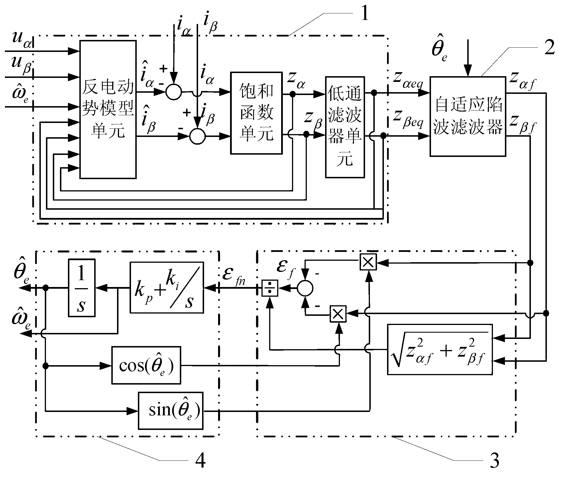
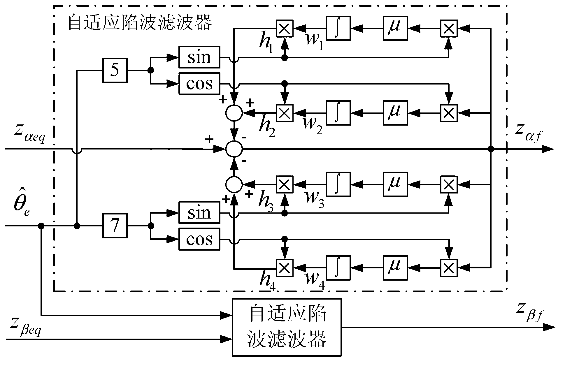
[0023] Specific embodiment one: see figure 1 To explain this embodiment, this is the built-in permanent magnet synchronous motor rotor position observation device based on adaptive filtering described in this mode, which is characterized in that it includes a sliding mode observer 1, an adaptive notch filter 2, a back-EMF return One unit 3 and quadrature phase-locked loop 4, sliding mode observer 1 is provided with the stator voltage u of the α axis in two-phase static coordinates α Input terminal, β axis stator voltage u β Input and rotor angular velocity observations Input terminal, the equivalent back EMF information z of the α axis of the sliding mode observer 1 αeq The equivalent back EMF information z of the output terminal and the α axis of the adaptive notch filter αeq The input terminal is connected, the β-axis equivalent back EMF information of the sliding mode observer 1 z βeq Β-axis equivalent back EMF information z of the output terminal and the adaptive notch filt...

specific Embodiment approach 2

[0024] Embodiment 2: This embodiment is a further definition of the built-in permanent magnet synchronous motor rotor position observation device based on adaptive filtering described in Embodiment 1. The sliding mode observer 1 includes a back-EMF model unit, a saturation Function unit, low-pass filter and two subtractors,

[0025] The back-EMF model unit is set with the stator voltage u of the α axis in two-phase static coordinates α Input terminal, β axis stator voltage u β Input terminal, rotor angular velocity observation Electromotive force information of input terminal and α axis z α Electromotive force information of the input terminal and β axis z β Equivalent back-EMF information at the input and α axis z αeq Equivalent back-EMF information at the input and β axis z βeq Input terminal, where the stator voltage u of the α axis in two-phase static coordinates α The input terminal is the stator voltage u of the α axis in the two-phase static coordinate of the sliding mode ...

specific Embodiment approach 3

[0026] Specific embodiment three: this embodiment is a further limitation of the built-in permanent magnet synchronous motor rotor position observation device based on adaptive filtering described in specific embodiment 1, the back electromotive force normalization link 3 includes two multipliers , Divider, adder and function processor,

[0027] The α-axis observation term z of a multiplier αf The input is the first α-axis observation term z of the back-EMF normalization unit 3. αf Input terminal, the multiplier is provided with a sine function input terminal, the input terminal is the sine function input terminal of the back-EMF normalization unit 3, and the signal output terminal of the multiplier is connected to one adder input terminal of the adder, and the other Β-axis observation term z of the multiplier βf The input is the first β-axis observation term z of the back-EMF normalization unit 3. βf Input terminal, the multiplier is provided with a cosine function input terminal...


PUM


Abstract

The invention provides a position observation device and a position observation method for a rotor of a built-in permanent magnetic synchronous motor based on adaptive filtering, and belongs to the field of motor control, solving the problem of the convectional model method that six-time harmonic pulsation observation error is contained in the acquired rotor position angle observation value. The position observation device and the position observation method are respectively an adaptive notch filtering filter signal processing device and an adaptive notch filtering filter signal processing method based on the least mean square algorithm, and the device and the method are used for removing the six-time rotor pulsation error in the control technology model method applicable to a middle and high speed position-free sensor permanent magnetic synchronous motor. The method comprises the following steps of: acquiring equivalent back electromotive force information through the model method; regulating through the adaptive notch filtering filter based on the least mean square algorithm; then carrying out normalization processing on the back electromotive force information; and finally acquiring a rotor position observation value through a phase-locked loop. The device and the method provided by the invention are simple and easy to implement, can be used for effectively inhibiting the influence of the six-time pulsation error in the rotor position observation value and improving the performance of the position-free sensor permanent magnetic synchronous motor, and are applicable to a permanent magnetic synchronous motor control system.

Description

Technical field [0001] The invention belongs to the field of motor control. Background technique [0002] In recent years, the permanent magnet synchronous motor speed control system has gradually become a research hotspot in the field of AC speed control transmission. The reason is that compared with traditional asynchronous motors, the advantages of permanent magnet synchronous motors are: simple structure, small size, light weight, reliable operation, high power density, good speed regulation performance, etc. Permanent magnet synchronous motors have become variable frequency adjustable Ideal for high-speed electric drive systems, its application areas are very wide. According to the different permanent magnet structure of the permanent magnet synchronous motor rotor, it can be divided into two types: surface mount type and built-in type. [0003] At present, in the application of high-performance permanent magnet synchronous motor speed control system, it is usually necessary...

Claims


Application Information

Patent Timeline
Patent Type & Authority Applications(China)
IPC IPC(8): H02P6/18H02P6/182H02P21/13
Inventor 王高林张国强李卓敏詹瀚林杨荣峰于泳徐殿国
Owner 哈工科讯(沈阳)智能工业技术有限公司
Why Eureka
Try Eureka