Position observation device and method for rotor of built-in permanent magnetic synchronous motor based on adaptive filtering
A technology of permanent magnet synchronous motor and self-adaptive filtering, applied in the direction of controlling electromechanical transmission, electronic commutator, controlling generator, etc., can solve problems such as 6th harmonic pulsation observation error, and achieve improved control performance and satisfactory control Performance, signal processing method is simple and easy to implement
- Summary
- Abstract
- Description
- Claims
- Application Information
AI Technical Summary
Problems solved by technology
Method used
Image
Examples
specific Embodiment approach 1
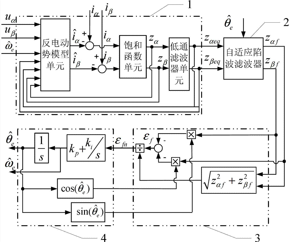
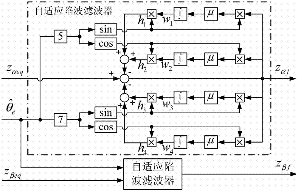
[0023] Specific implementation mode one: see figure 1 Describe this embodiment, this is the built-in permanent magnet synchronous motor rotor position observation device based on adaptive filtering described in the method, it is characterized in that it includes a sliding mode observer 1, an adaptive notch filter 2, a back EMF return A chemical unit 3 and a quadrature phase-locked loop 4, the sliding mode observer 1 is provided with the stator voltage u of the α-axis in the two-phase static coordinates α Stator voltage u at input, β-axis β Input and rotor angular velocity observations At the input end, the equivalent back EMF information z of the α-axis of the sliding mode observer 1 αeq Equivalent back EMF information z at the output to the α axis of the adaptive notch filter αeq The input terminal is connected, the β-axis equivalent back EMF information z of the sliding mode observer 1 βeq The β-axis equivalent back EMF information z of the output terminal and the adapt...
specific Embodiment approach 2
[0024] Embodiment 2: This embodiment is a further limitation of the built-in permanent magnet synchronous motor rotor position observation device based on adaptive filtering described in Embodiment 1. The sliding mode observer 1 includes a back electromotive force model unit, a saturation function unit, low-pass filter and two subtractors,
[0025] The back electromotive force model unit is set with the stator voltage u of the α-axis in the two-phase stationary coordinates α Stator voltage u at input, β-axis β Input terminal, rotor angular velocity observation value The electromotive force information z of the input terminal and the α axis α The electromotive force information z of the input terminal and the β axis β The equivalent back electromotive force information z of the input terminal and the α axis αeq The equivalent back electromotive force information z of the input terminal and the β axis βeq At the input terminal, the stator voltage u of the α-axis in the two...
specific Embodiment approach 3
[0026] Specific embodiment three: this embodiment is a further limitation of the built-in permanent magnet synchronous motor rotor position observation device based on adaptive filtering described in specific embodiment one, and the back electromotive force normalization link 3 includes two multipliers , dividers, adders, and function processors,
[0027] A multiplier for the α-axis observation term z αf The input terminal is the first α-axis observation item z of the back EMF normalization unit 3 αf Input terminal, the multiplier is provided with a sine function input terminal, which is the sine function input terminal of the back electromotive force normalization unit 3, and the signal output terminal of the multiplier is connected with an addend input terminal of the adder, and the other The β-axis observation term z of the multiplier βf The input end is the first β-axis observation item z of the back EMF normalization unit 3 βf Input terminal, the multiplier is provided...
PUM
 Abstract
Description
Claims
Application Information
 - R&D
- Intellectual Property
- Life Sciences
- Materials
- Tech Scout
- Unparalleled Data Quality
- Higher Quality Content
- 60% Fewer Hallucinations
Browse by: Latest US Patents, China's latest patents, Technical Efficacy Thesaurus, Application Domain, Technology Topic, Popular Technical Reports.
© 2025 PatSnap. All rights reserved.Legal|Privacy policy|Modern Slavery Act Transparency Statement|Sitemap|About US| Contact US: help@patsnap.com


