Curtain wall structure

A curtain wall and glass technology, applied to walls, building components, building structures, etc., can solve problems such as increased air-conditioning load and indoor temperature rise, and achieve the effects of reducing heat load, improving the environment, and suppressing the reduction of light

Active Publication Date: 2013-07-10
株式会社骊住集团 +1
View PDF6 Cites 4 Cited by
  • Summary
  • Abstract
  • Description
  • Claims
  • Application Information

AI Technical Summary

Problems solved by technology

[0007] On the other hand, when the blinds or blinds are not closed, sunlight enters the room through the glass. Therefore, in summer, the indoor temperature rises due to the heat of the sun, and the load on the air conditioner increases.

Method used


Image

  • Curtain wall structure
  • Curtain wall structure
  • Curtain wall structure

Examples


no. 1 example

[0054] (Structure of shutter assembly 1)

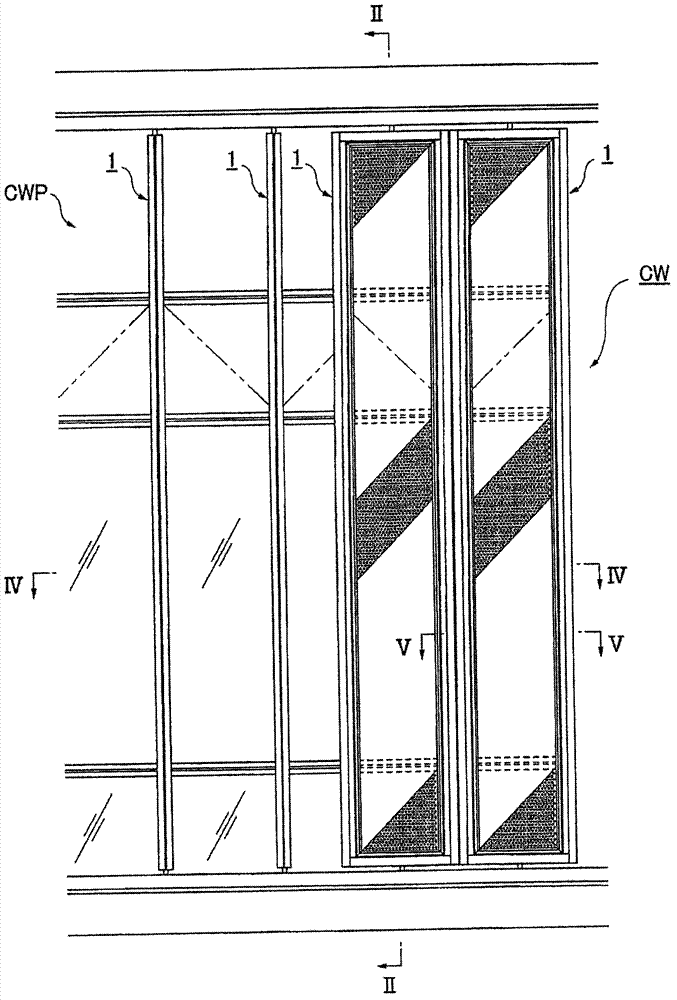
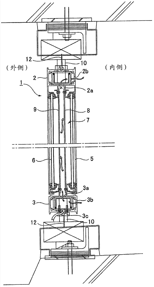
[0055] In detail, as image 3 and Figure 5 As shown, the shutter assembly 1 of the first embodiment is surrounded by an upper frame 2, a lower frame 3, and left and right vertical frames 4, 4 in a frame, and two pieces of glass 5, 6 are fitted and supported parallel to the frame surface. An air layer 7 is set between the two glasses, and, in the above-mentioned air layer 7, on the above-mentioned frames 2, 3, 4, spaced apart by fixing screws, for example Two perforated panels 8,9.

[0056] Such as image 3 As shown, the above-mentioned upper frame 2 and the lower frame 3 are respectively set as hollow sections, and are formed with air communication ports 2a, 3a communicating with the above-mentioned air layer 7 in the hollow sections, and in the above-mentioned two pieces of glass 5, 6 Air communication ports 2b, 3b communicating with the outside of the frame are formed on the surface of a glass 5 side. In addition, the lower fr...

no. 2 example

[0075] Such as Figure 7 As shown, in the louver assembly 1 of the second embodiment, two perforated panels 8, 9 are arranged in the above-mentioned air layer 7, and the perforated panel 8 disposed on one side of a glass 5 is colored in white. The perforated panel 9 arranged on one side of the other glass 6 is colored in black.

[0076] Thus, in summer mode, if Figure 7 As shown in (A), each louver assembly 1 is rotated, one glass 5 is arranged facing the outside, and the other glass 6 is arranged facing the inside, and the perforated panel 8 which has been colored in white is arranged outside, and the The perforated panel 9 colored in black is disposed inside.

[0077] Thus, the sunlight incident on the shutter assembly 1 passes through a glass 5 and irradiates to the outer perforated panel 8 to generate radiant heat. Moreover, since the perforated panel 8 is colored in white, it reflects most of the sun's rays. Light. In addition, sunlight passing through the openings o...

no. 3 example

[0081] Such as Figure 8 As shown, the louver assembly 1 of the third embodiment is equipped with a perforated panel 8 in the air layer 7. For the perforated panel 8, the surface 8A on the side of the first glass 5 is colored in white, and the other panel is colored white. The surface 8B on the side of the glass 6 is colored in black. In addition, the above-mentioned perforated panel 8 may be formed by bonding and laminating a white-based panel and a black-based panel.

[0082] Also, in summer mode, if Figure 8 As shown in (A), each shutter assembly 1 is rotated, one glass 5 is arranged facing outward, the other glass 6 is arranged facing inward, and the surface 8A of the perforated panel 8 that is colored with white is arranged facing outward, The surface 8B colored in black is arranged facing inward.

[0083] Thus, the sunlight entering the louver assembly 1 passes through the glass 5 and irradiates the perforated panel 8 to generate radiant heat, and since the outer sur...


PUM


Abstract

to drastically reduce energy consumption by reducing the heat load from solar radiated heat during summer and efficiently absorbing solar radiated heat during winter, while suppressing the reduction in light volume inside a room. [Solution] A curtain wall structure is provided wherein: a plurality of louver units (1, 1...) are arranged at prescribed intervals in a horizontal direction on the outside of a curtain wall panel (CWP); each louver unit (1) has two sheets of glass (5, 6) arranged inside a frame, with an air layer (7) disposed therebetween; two porous panels (8, 9) with a plurality of holes are arranged inside the air layer (7) at intervals and parallel to the two sheets of glass (5, 6); the surface of each porous panel (8, 9) on one sheet of glass (5) side is colored a whitish color and the surface on the other sheet of glass (6) side is colored blackish; air communication ports (2b, 3b) that communicate between the air layer and the louver unit exterior are each disposed on the top and bottom end of the surface on the one sheet of glass (5) side, and the curtain wall structu.

Description

technical field [0001] The present invention relates to a curtain wall structure that realizes significant energy saving by reducing heat load generated by solar radiation heat in summer and efficiently recovering solar radiation heat in winter. Background technique [0002] At present, various types of curtain wall structures called so-called double layers have been proposed to reduce the heat load generated by the heat of sunlight irradiated from glass windows and realize energy saving. [0003] Specifically, the following patent document 1 discloses a curtain wall structure in which the window part is set as a double-layer structure composed of outdoor side glass and indoor side glass, an air layer is provided between the two glasses, and the window part The upper and / or lower parts of the upper and / or lower parts are respectively equipped with a flow path switching device, and a curtain is arranged in the air layer. In addition, Patent Document 2 below discloses an exte...

Claims


Application Information

Patent Timeline
Patent Type & Authority Applications(China)
IPC IPC(8): E04B1/74
CPCE04B1/74E04B2/88E04C2/525F24S20/63F24S50/80F24S2020/183Y02B10/20Y02E10/40E04B1/7645Y02E10/44
Inventor 石井久史信太洋行马郡文平野城智也藤井逸人
Owner 株式会社骊住集团
Why Eureka
Try Eureka