Electromagnetic micro jet device

A micro-spraying and electromagnetic technology, applied in the direction of electrostatic spraying devices, spraying devices, etc., can solve the problems of inapplicability, inapplicable micro-spraying of metal materials, and the frequency should not be too high, so as to achieve stable and stable liquid supply pressure and simplify the mechanical structure Effect

A micro-spraying and electromagnetic technology, applied in the direction of electrostatic spraying devices, spraying devices, etc., can solve the problems of inapplicability, inapplicable micro-spraying of metal materials, and the frequency should not be too high, so as to achieve stable and stable liquid supply pressure and simplify the mechanical structure Effect

CN103203294AActive Publication Date: 2013-07-17XIAMEN UNIV

Image

  • Electromagnetic micro jet device
  • Electromagnetic micro jet device
  • Electromagnetic micro jet device

Examples


Embodiment Construction

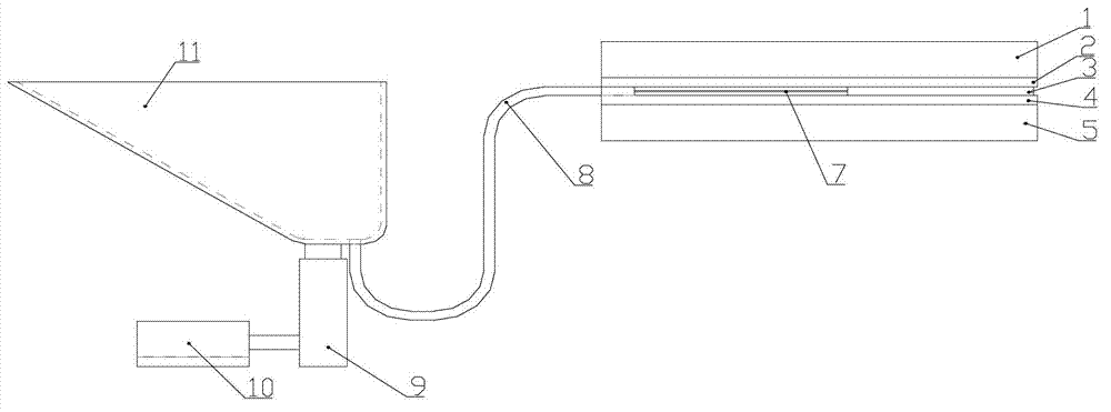
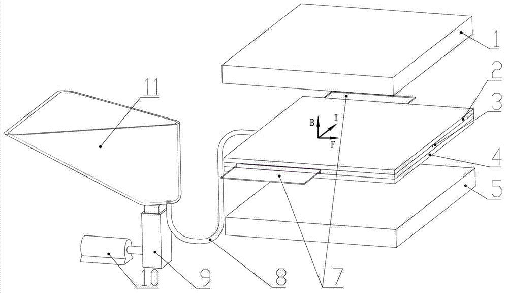
[0015] see Figure 1~3 , the embodiment of the present invention is provided with an upper magnet 1, an injection cavity (including an upper cover plate 2, a middle partition plate 3 with a nozzle and a lower cover plate 4), a lower magnet 5, an electrode 7, a liquid supply pipe 8, a lift Table 9, stepper motor 10, liquid supply tank 11 and pulse current device 12.

[0016] The upper cover plate 2, the middle partition plate 3 with nozzles and the lower cover plate 4 are installed together to form a spray chamber 6. One side of the middle partition plate 3 is provided with a liquid inlet 31, and the other side of the middle partition plate 3 is provided with a nozzle for liquid outlet. 32. The upper magnet 1 and the lower magnet 5 are placed on the upper and lower surfaces of the injection cavity, so that the injection cavity 6 is in the magnetic field B. The pulse current device 12 is used to generate pulse current, and its positive and negative poles are connected with the...


PUM


Abstract

The invention discloses an electromagnetic micro jet device, and relates to a micro jet device. The electromagnetic micro jet device is suitable for jet of metal liquid as required, and is provided with an upper magnet, a jet cavity, a lower magnet, electrodes, a liquid feed pipe, a liquid feed tank, a lifting mechanism, a stepping motor and a pulse current device, wherein the upper magnet and the lower magnet are fixed on the upper surface and the lower surface of the jet cavity respectively; the jet cavity is provided with a liquid inlet and a liquid nozzle; the electrodes are arranged on the two sides of the jet cavity and stretch into the jet cavity; one end of the liquid feed pipe is communicated with an inner cavity of the jet cavity; the other end of the liquid feed pipe is communicated with the liquid feed tank; an input end of the lifting mechanism is connected with the stepping motor; an output end of the lifting mechanism is connected with the liquid feed tank; and the two ends of the pulse current device are connected with the electrodes.

Description

technical field [0001] The invention relates to a micro-spraying device, in particular to an electromagnetic micro-spraying device for liquid metal micro-spraying. Background technique [0002] With the development of microelectronic packaging technology, there are more and more processes that need to use fluid materials in the microelectronics industry, which promotes the rapid development of fluid micro-jet technology. Fluid microjet technology is a key technology in microelectronic packaging. It can be structured to form points, lines, surfaces (coating) and various graphics, and is widely used in chip fixing, package flipping and chip coating. This technology is the process of precisely dispensing fluids in a controlled manner to transfer ideally sized fluids (such as solder, conductive glue, epoxies, and adhesives, etc.) to workpieces (chips, electronic components, etc.) ) in the appropriate position to achieve mechanical or electrical connections between components. ...

Claims


Application Information

Patent Timeline
17 Jul 2013
Publication
CN103203294A
IPC
B05B5/00
Inventors
孙道恒; 罗志伟