Continuous-walking type hydraulic pushing device

A hydraulic and jacking technology, applied in the direction of hoisting device, winch device, etc., to achieve the effect of low cost, simple and reasonable structure, and saving man-hours

Inactive Publication Date: 2013-07-17
TONGJI UNIV
View PDF7 Cites 11 Cited by
  • Summary
  • Abstract
  • Description
  • Claims
  • Application Information

AI Technical Summary

Problems solved by technology

[0004] The purpose of the present invention is to overcome the deficiencies of the above-mentioned technologies, solve the problem of continuous jacking when hydraulic cylinders are multi-stroke superimposed in long-distance jacking construction, and provide a continuous walking hydraulic jacking device

Method used


Image

  • Continuous-walking type hydraulic pushing device
  • Continuous-walking type hydraulic pushing device
  • Continuous-walking type hydraulic pushing device

Examples


Embodiment 1

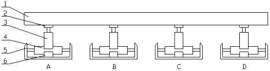
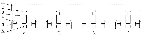
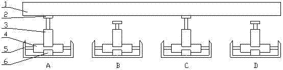
[0023] Embodiment 1: A continuous walking hydraulic jacking device, including a jacking tray 2 , a longitudinal hydraulic jacking cylinder 3 , a horizontal hydraulic jacking cylinder 4 , a cylinder base 5 and a cylinder support seat 6 .

[0024] The push pallet 2 is welded on the piston rod of the longitudinal hydraulic push cylinder 3 . The cylinder body of longitudinal hydraulic jacking cylinder 3 is vertically welded in the cylinder body center of horizontal hydraulic jacking cylinder 4, and can move left and right with the cylinder body of horizontal hydraulic jacking cylinder 4. The cylinder base 5 is welded with the piston rods at both ends of the horizontal hydraulic push cylinder 4 . The horizontal hydraulic jacking cylinder 4 rests on the oil cylinder support base 6 , and the cylinder body of the horizontal hydraulic pressure thrust cylinder 4 can move left and right relative to the oil cylinder support base 6 . Each hydraulic jacking cylinder is controlled by a comp...


PUM


Abstract

The invention relates to a continuous-walking type hydraulic pushing device. The continuous-walking type hydraulic pushing device comprises a pushing tray, a longitudinal hydraulic pushing cylinder, a lateral hydraulic pushing cylinder, a cylinder base and a cylinder supporting seat. The longitudinal hydraulic pushing cylinder and the lateral hydraulic pushing cylinder respectively comprise cylinder bodies and piston rods, and the pushing tray is welded on the piston rod of the longitudinal hydraulic pushing cylinder. The cylinder body of the longitudinal hydraulic pushing cylinder is vertically welded at the center of the cylinder body of the lateral hydraulic pushing cylinder, and can move to the right and to the left along with the lateral hydraulic pushing cylinder. The cylinder base is welded with the piston rods at two ends of the lateral hydraulic pushing cylinder. The lateral hydraulic pushing cylinder is arranged on the cylinder supporting seat, and can move to the right and to the left corresponding to the cylinder supporting seat. The longitudinal hydraulic pushing cylinder and the lateral hydraulic pushing cylinder are connected with a computer respectively and control to realize synchronically-coordinated actions through a computer control system. The continuous-walking type hydraulic pushing device is simple and reasonable in structure, convenient to process and manufacture, and low in production cost.

Description

technical field [0001] The invention relates to a hydraulic pushing device, in particular to a continuous walking hydraulic pushing device. Background technique [0002] In the field of modern engineering construction, hydraulic cylinder jacking devices are widely used. When the distance of pushing is relatively long, it is necessary to superimpose the strokes of the hydraulic cylinder for multiple pushing to complete the whole pushing construction task. Usually, when using the hydraulic cylinder push technology to push heavy objects, there must be a reaction force seat behind the cylinder. The superimposed construction of the push stroke needs to repeatedly dismantle the reaction seat, move it forward and install and fix it, which is cumbersome, time-consuming and labor-intensive. In addition, in the process of repeated installation and disassembly of the reaction force seat, it is easy to cause deformation and wear of the pushing track. The reaction force seat itself wil...

Claims


Application Information

Patent Timeline
Patent Type & Authority Applications(China)
IPC IPC(8): B66F19/00
Inventor 卞永明李安虎刘广军蒋佳朱利静徐新明
Owner TONGJI UNIV
Why Eureka
Try Eureka