
Root pressure grouting pile and construction method thereof

A construction method and technology of cast-in-situ piles, which are applied in sheet pile walls, foundation structure engineering, construction, etc., can solve the problems of high construction cost, difficulty in construction, and difficulty in construction of pile foundations, so as to reduce construction costs and improve construction efficiency. The effect of low construction cost and less material

Inactive Publication Date: 2013-07-17
HUAIYIN INSTITUTE OF TECHNOLOGY
View PDF6 Cites 14 Cited by
  • Summary
  • Abstract
  • Description
  • Claims
  • Application Information

AI Technical Summary

Problems solved by technology

However, in actual construction, the longer the pile foundation is, the more difficult the construction is; the larger the diameter of the pile foundation, the more building materials are required, and the higher the construction cost of the pile foundation; the final pressure-bearing effect of the pile foundation is improved. Compared with the construction difficulty and construction cost of the pile foundation, it is disproportionate
This method of simply increasing the diameter or length of the pile foundation needs to consume a large amount of concrete, which is difficult to construct and not economical

Method used


Image

  • Root pressure grouting pile and construction method thereof
  • Root pressure grouting pile and construction method thereof
  • Root pressure grouting pile and construction method thereof

Examples


Embodiment 1

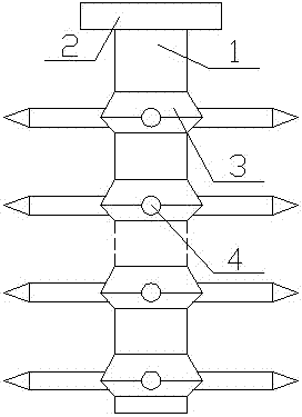
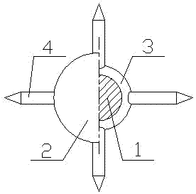
[0031] combine figure 1 with figure 2 As shown, the present invention includes a cylindrical pile foundation 1, and also includes a cap surface 2 arranged on the top of the pile foundation 1, and a plurality of root keys 4 are arranged on the cylindrical surface of the pile foundation 1; or the cylindrical surface of the pile foundation 1 A supporting plate 3 protruding from the center of the circle is provided, and the plurality of root keys 4 are connected to the supporting plate 3; the root keys 4 are perpendicular to the pile foundation 1; the end of the root key 4 away from the pile foundation 1 is a cone structure; the root keys 4 arranged on the cylindrical surface of the pile foundation 1 are arranged in multiple layers from top to bottom; the number of root keys 4 set on each support plate 3 is at least 3, and the root keys 4 are equally divided into a circle of the support plate 3; the distance between the root keys 4 of two adjacent layers is in the range of 1 to ...

Embodiment 2

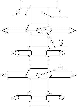
[0034] combine image 3 with Figure 4 As shown, the present invention includes a cylindrical pile foundation 1, and also includes a cap surface 2 arranged on the top of the pile foundation 1, and a plurality of root keys 4 are arranged on the cylindrical surface of the pile foundation 1; or the cylindrical surface of the pile foundation 1 A supporting plate 3 protruding from the center of the circle is provided, and the plurality of root keys 4 are connected to the supporting plate 3; the root keys 4 are perpendicular to the pile foundation 1; the end of the root key 4 away from the pile foundation 1 is a cone structure; the root keys 4 arranged on the cylindrical surface of the pile foundation 1 are arranged in multiple layers from top to bottom; the number of root keys 4 set on each support plate 3 is at least 3, and the root keys 4 are equally divided into a circle of the support plate 3; the distance between the root keys 4 of two adjacent layers is in the range of 1 to ...


PUM


Abstract

The invention discloses a root pressure grouting pile comprising a cylindrical pile foundation, wherein the root pressure grouting pile further comprises a bearing platform surface arranged on the top of the cylindrical pile foundation, and a plurality of root keys are arranged on the cylindrical surface of the pile foundation; or concentrically projecting support disks are arranged on the cylindrical surface of the pile foundation, and the plurality of root keys are connected with the support disks. The construction method comprises the following steps of: firstly, digging the earthwork of a first segment of pile hole, and extruding the holes of the support disks after forming the first segment of pile hole; horizontally knocking the root keys out of the holes of the support disks, respectively, and reserving the inner ends of the root keys in the pile hole; building a supporting wall template along the side wall of the pile hole, and pouring supporting wall concrete; repeating the steps, circularly working downwards segment by segment until the depth of the pile hole reaches a required demand; and hanging a preformed pile foundation reinforcement cage in a supporting wall hole, and pouring the pile body of the pile foundation. Therefore, in the pile structure built by the invention, the stress area of the pile foundation is increased, the bearing pressure of the pile foundation is improved, the construction materials are few, the construction is convenient, and the construction cost is lowered.

Description

technical field [0001] The invention relates to the field of civil engineering, in particular to a root-type pressure-bearing cast-in-place pile and a construction method thereof. Background technique [0002] In the field of construction, pile foundations are usually used for bearing pressure, and pile foundations bear pressure through the joint action of pile side resistance and pile end resistance. The bearing capacity of the pile foundation is related to the resistance provided by the pile side and pile end. By increasing the diameter of the pile foundation or the length of the pile foundation, that is, by increasing the stressed area, the pile side resistance or pile end resistance of the pile foundation can be improved. , thereby increasing the bearing capacity of the pile foundation. However, in actual construction, the longer the pile foundation is, the more difficult the construction is; the larger the diameter of the pile foundation, the more building materials ar...

Claims


Application Information

Patent Timeline
Patent Type & Authority Applications(China)
IPC IPC(8): E02D5/48E02D5/50
Inventor 龚成中何春林
Owner HUAIYIN INSTITUTE OF TECHNOLOGY
Learn More