
Supercharger engine hot end heat insulating shield assembly

A technology of supercharged engine and heat shield, which is applied to engine components, machines/engines, mechanical equipment, etc., can solve the problems of difficulty in ensuring strength and modal requirements, high installation process requirements, and many installation points. The effect of cost control, reduction of processing requirements, and prolongation of service life

Active Publication Date: 2013-07-17
CHONGQING CHANGAN AUTOMOBILE CO LTD
View PDF8 Cites 8 Cited by
  • Summary
  • Abstract
  • Description
  • Claims
  • Application Information

AI Technical Summary

Problems solved by technology

[0003] Existing supercharged engine hot end heat shield assembly, including exhaust manifold heat shield, supercharger heat shield and three-way catalytic converter The heat shield, the exhaust manifold heat shield is installed on the exhaust manifold, the supercharger heat shield is installed on the supercharger, and the three-way catalytic converter heat shield is installed on the three-way catalytic converter. The heat shield independently insulates the corresponding parts, so that the heat shield assembly has more components, the structure is more complicated, and the installation points are more, which makes the installation process more demanding, it is difficult to ensure the strength and modal requirements, and the cost is also higher

Method used


Image

  • Supercharger engine hot end heat insulating shield assembly
  • Supercharger engine hot end heat insulating shield assembly
  • Supercharger engine hot end heat insulating shield assembly

Examples


Embodiment Construction

[0016] The present invention will be further described below in conjunction with accompanying drawing.

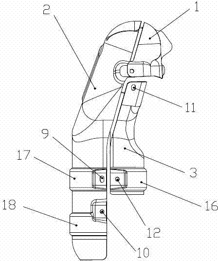
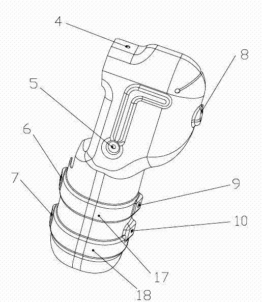
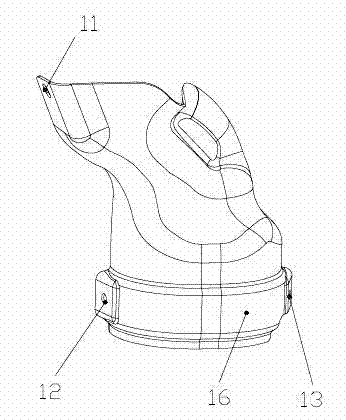
[0017] Such as Figure 1 to Figure 4 The hot end heat shield assembly of the supercharged engine includes an exhaust manifold heat shield (not shown in the figure), a supercharger heat shield 1 and a three-way catalytic converter heat shield, and the supercharger heat shield Both the heat shield 1 and the heat shield of the three-way catalytic converter are layered structures, the upper and lower layers are hot-dipped aluminum plates, and the middle layer is ceramic fiber cardboard; the heat shield of the three-way catalytic converter is installed on the left side of the supercharger 14 by the upper part, The lower part is composed of the three-way catalytic converter upper cover 2 installed on the left side of the three-way catalytic converter 15 and the lower three-way catalytic converter cover 3 installed on the right side of the three-way catalytic converter 15; the sup...


PUM


Abstract

The invention discloses a supercharger engine hot end heat insulating shield assembly which comprises an exhaust manifold heat insulating shield, a supercharger heat insulating shield and a three-way catalyst heat insulating shield. Both the supercharger heat insulating shield and the three-way catalyst heat insulating shield are in a layered structure, upper layers and lower layers of the two are hot-dipping aluminum plates, and middle layers of the two are ceramic fiber paper plates. The three-way catalyst heat insulating shield is formed by an upper three-way catalyst shield and a lower three-way catalyst shield, wherein the upper portion of the upper three-way catalyst shield is mounted on the left side of a supercharger, the lower portion of the lower three-way catalyst shield is mounted on the left side of a three-way catalyst, and the lower three-way catalyst shield is mounted on the right side of the three-way catalyst. The supercharger heat insulating shield is arranged above the three-way catalyst heat insulating shield, mounted on the right side of the supercharger and connected with the upper portion of the three-way catalyst shield via two mounting points. By the supercharger engine hot end heat insulating shield assembly, the supercharger and the three-way catalyst are integrally subjected to heat insulation, noise reduction and protection, strength can be guaranteed and modal requirements can be met, processing and manufacturing are enabled to be easy, and the mounting is enabled to be convenient.

Description

technical field [0001] The invention relates to a component of an exhaust system of an automobile engine, in particular to a hot-end heat shield assembly of a supercharged engine. Background technique [0002] According to the temperature, the engine exhaust system is divided into hot end and cold end. The former includes exhaust manifold, supercharger and three-way catalytic converter, and the latter includes muffler with accessory assembly and related pipelines. Usually, the temperature of the hot end of the engine exhaust system is high, and it is necessary to add a heat shield to achieve heat insulation, noise reduction and safety protection functions. For supercharged engines (especially supercharged gasoline engines), the temperature at the hot end of the exhaust system is significantly higher than that of naturally aspirated gasoline engines, and the maximum temperature at the hot end of the engine can reach above 1000°C, which is the most serious area of ​​engine hea...

Claims


Application Information

Patent Timeline
IPC IPC(8): F01N3/28F02B39/00
Inventor 陈向阳陈生超戴永蓥李良国李冰朱国兵
Owner CHONGQING CHANGAN AUTOMOBILE CO LTD
Learn More