
Device for realizing LED (Light Emitting Diode) encapsulation

A technology of LED packaging and LED chips, which is applied in the field of LED light sources, can solve the problems of unfavorable promotion and use of LED lamps, increased production cost of LED lamps, high production cost and high use cost, and achieves shortened heat conduction path, good heat dissipation effect, and convenient batch production The effect of production

Active Publication Date: 2013-07-17
CHONGQING SILIAN OPTOELECTRONICS SCI & TECH
View PDF6 Cites 2 Cited by
  • Summary
  • Abstract
  • Description
  • Claims
  • Application Information

AI Technical Summary

Problems solved by technology

This structure increases the production cost of LED lamps, and while the LED lamps are working, the electric fan also works, the power consumption increases, and the use cost also increases accordingly, especially the life of the electric fan is far lower than that of the LED chip. Life expectancy requires frequent maintenance and replacement of electric fans, and the maintenance cost also increases, resulting in increased costs, which is not conducive to the promotion and use of LED lamps
[0005] 3. Use the heat exchange tube cooling method similar to refrigeration equipment to dissipate heat. This structure needs to be equipped with a refrigeration device, which conducts heat exchange and heat dissipation through the fluid flowing through the heat exchange tube. In this way, not only the overall structure of the LED lamp increases, but also And the structure is more complicated, and the production cost and use cost are also higher, which is not conducive to the popularization and use of LED lamps

Method used


Image

  • Device for realizing LED (Light Emitting Diode) encapsulation
  • Device for realizing LED (Light Emitting Diode) encapsulation
  • Device for realizing LED (Light Emitting Diode) encapsulation

Examples


Embodiment Construction

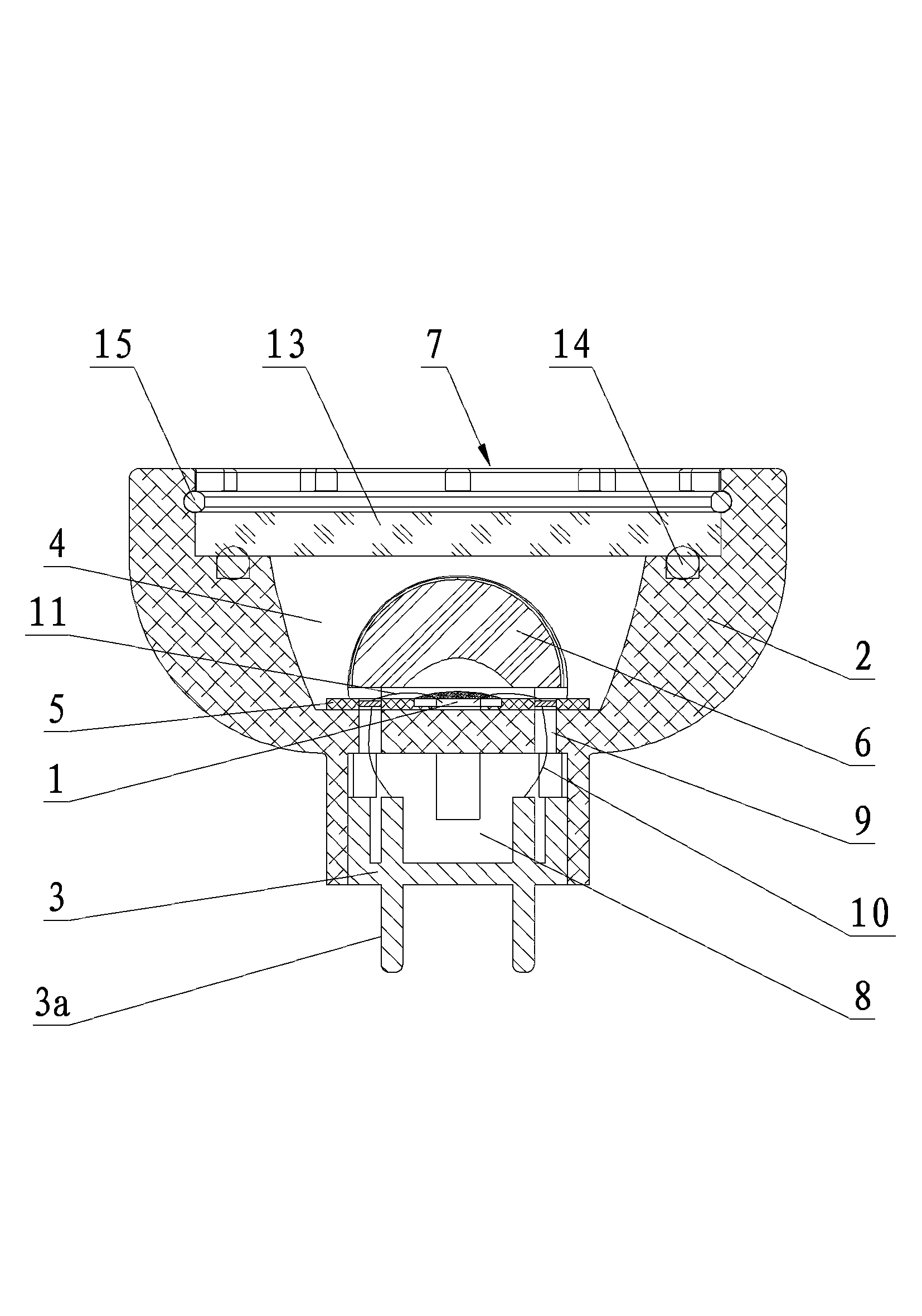
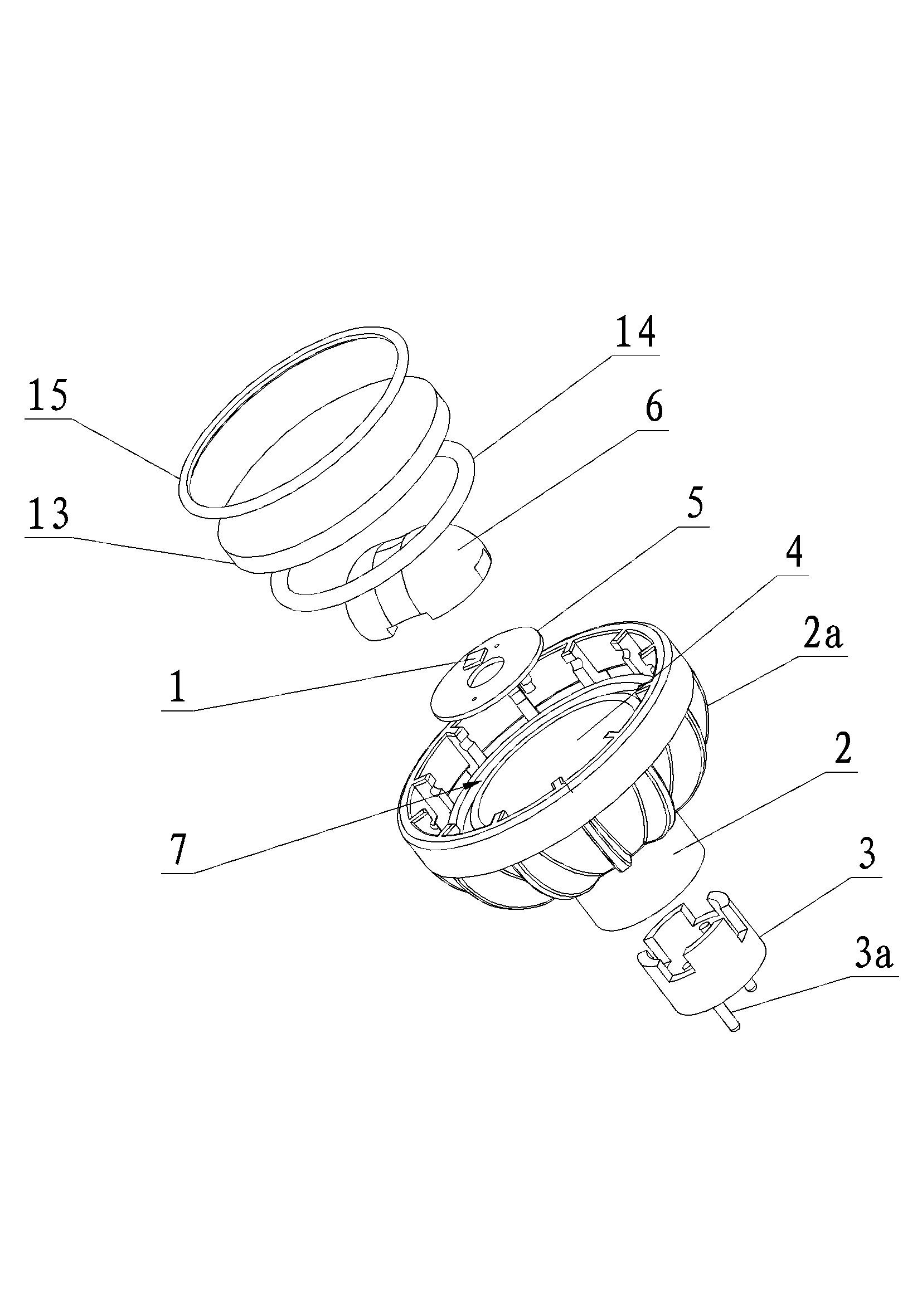
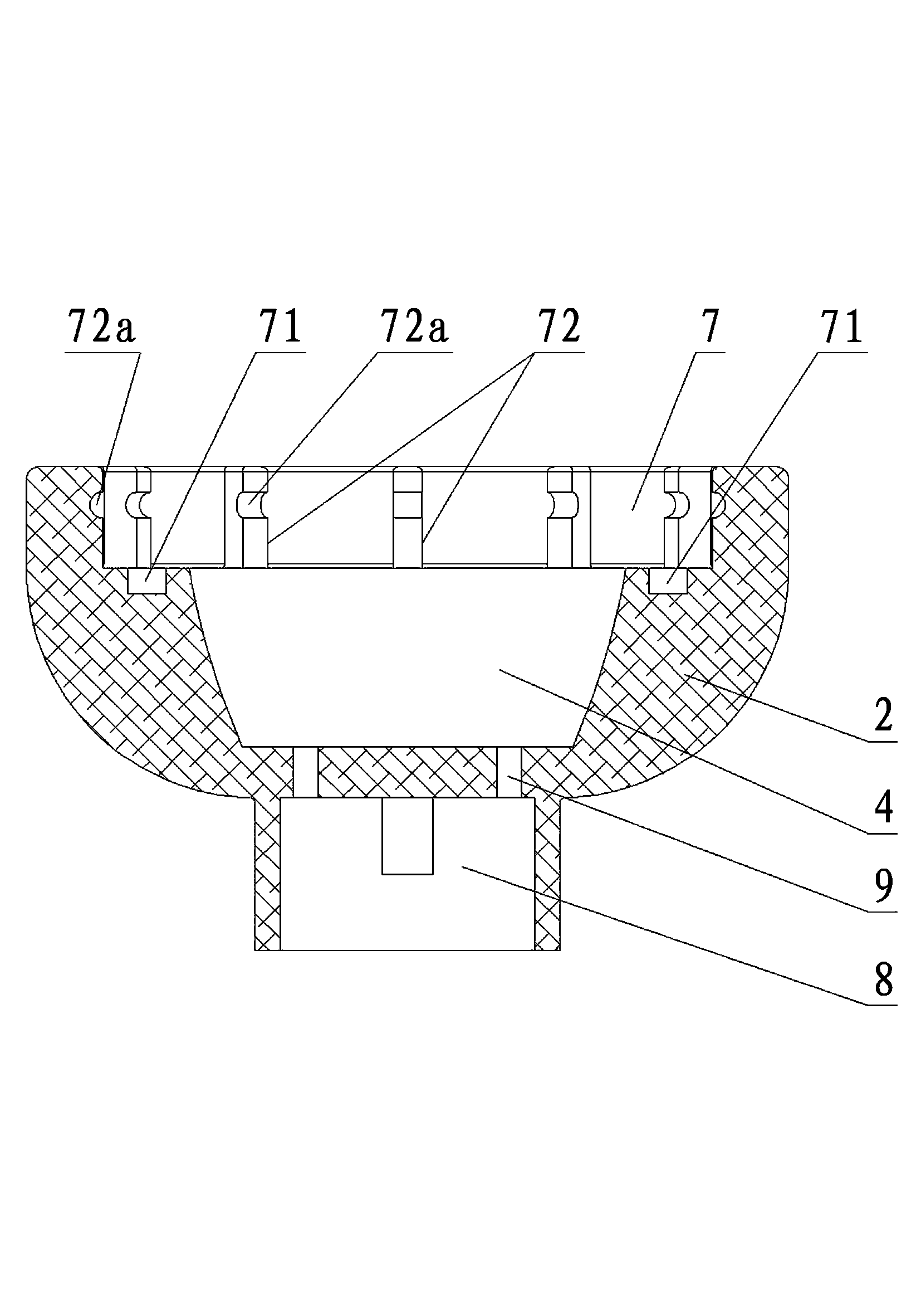
[0027] see Figure 1 to Figure 5 , an embodiment of an implementation device for LED packaging, including an LED chip 1, a heat sink 2 and an electrical connector 3, wherein the light-emitting surface of the LED chip 1 is coated with phosphor powder 16, and the phosphor powder 16 is excited by the LED chip 1 to emit white light ; The outer wall of the radiator 2 is provided with a number of cooling fins 2a to ensure the cooling effect; the electrical connector 3 is provided with pins 3a for connecting to an external power supply. One end of the radiator 1 is a large end, and the other end is a small end. The end face of the large end of the radiator is axially provided with a light source chamber 4 in a concave cavity, and a center with a groove 5a is arranged in the light source chamber 4. Insulation layer 5, the insulation layer 5 is bonded to the bottom wall of the light source chamber 4, and the LED chip 1 is fixed in the groove 5a of the insulation layer. The material of ...


PUM


Abstract

The invention relates to a device for realizing LED (Light Emitting Diode) encapsulation, which comprises an LED chip, a radiator and an electric connecting piece, wherein one end of the radiator is a big end; the other end of the radiator is a small end; a reentrant light source chamber is axially arranged on the end face of the big end of the radiator; an insulating layer with a groove being arranged in the center is arranged in the light source chamber, and is fit with the bottom wall of the light source chamber; the LED chip is fixed in the groove of the insulating layer; one side, used for fixing the LED chip, of the insulating layer is provided with a lens and forms sealing; an inner stopping opening is arranged on the opening end of the light source chamber, is provided with a light emitting cover assembly and forms sealing; an electric room is axially arranged on the end face of the small end of the radiator; a wire passing hole is arranged between the electric room and the light source chamber; the electric connecting piece is arranged in the electric room; and the wire of the electric connecting piece passes the wire passing hole and is connected with the insulating layer in the light source chamber. According to the device, heat dispersion performance is good, a lighting effect is high, service life is long, production cost is saved, assembly is convenient during the production of lamps, production process is simplified, and batch production is facilitated.

Description

technical field [0001] The invention relates to an LED light source, in particular to a device for realizing LED encapsulation. Background technique [0002] With the continuous promotion of LED green energy-saving lighting, the demand for LED lamps is also increasing. At the same time, the requirements for LED light sources are getting higher and higher. Due to the high heat generated by LED chips during operation, the heat dissipation of LED lamps must be solved. The current heat dissipation of LED lamps mainly includes the following methods: [0003] 1. Take active heat dissipation, fix the packaged LED light source on the printed board, connect the printed board to the radiator, conduct the heat generated by the LED chip to the radiator through the printed board, and use the radiator to dissipate heat into the air to Realize the cooling of the LED chip. However, since the printed board of this structure is a multi-layer structure, and the printed board is connected to ...

Claims


Application Information

Patent Timeline
Patent Type & Authority Applications(China)
IPC IPC(8): F21S2/00F21V29/00F21V31/00F21V23/06F21Y101/02F21K9/23F21K9/235F21V29/50F21V29/74F21Y115/10
Inventor 胡栋黎朝进
Owner CHONGQING SILIAN OPTOELECTRONICS SCI & TECH
Learn More