Driver casing, luminous device and lamp

A light-emitting device and driver technology, which is applied to lighting devices, components of lighting devices, cooling/heating devices of lighting devices, etc., can solve the problems of leakage of perfusion heat-dissipating glue and difficult areas to cover, etc., and achieve the effect of improving heat dissipation

Pending Publication Date: 2013-07-17
OSRAM GMBH
View PDF7 Cites 1 Cited by
  • Summary
  • Abstract
  • Description
  • Claims
  • Application Information

AI Technical Summary

Problems solved by technology

However, the disadvantage of this solution is that since the sensitive E-cap is located close to the central area of ​​the light engine, and since the E-cap uses electrical connecting wires for electrical connection, this area is difficult to be covered by the potting material
In addition, the

Method used


Image

  • Driver casing, luminous device and lamp
  • Driver casing, luminous device and lamp
  • Driver casing, luminous device and lamp

Examples


Embodiment Construction

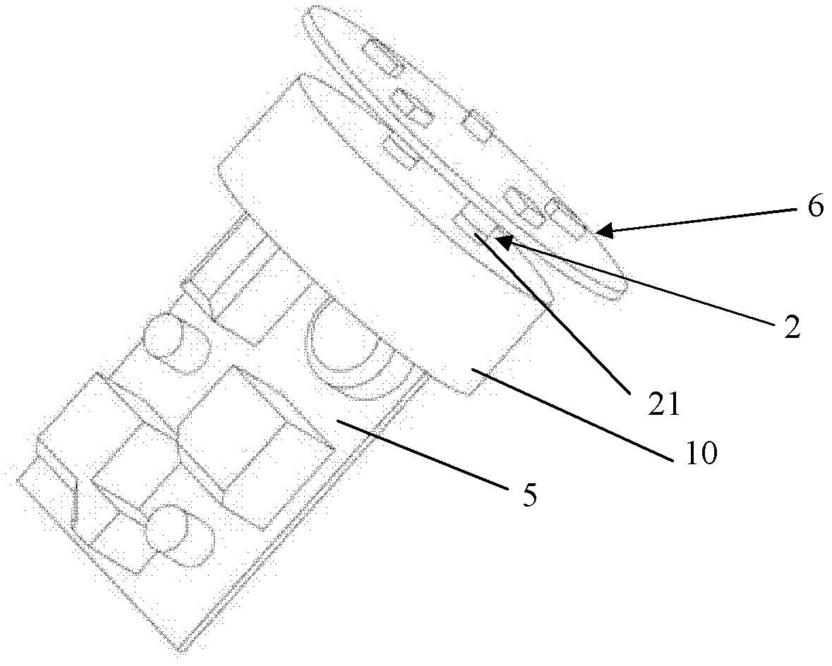
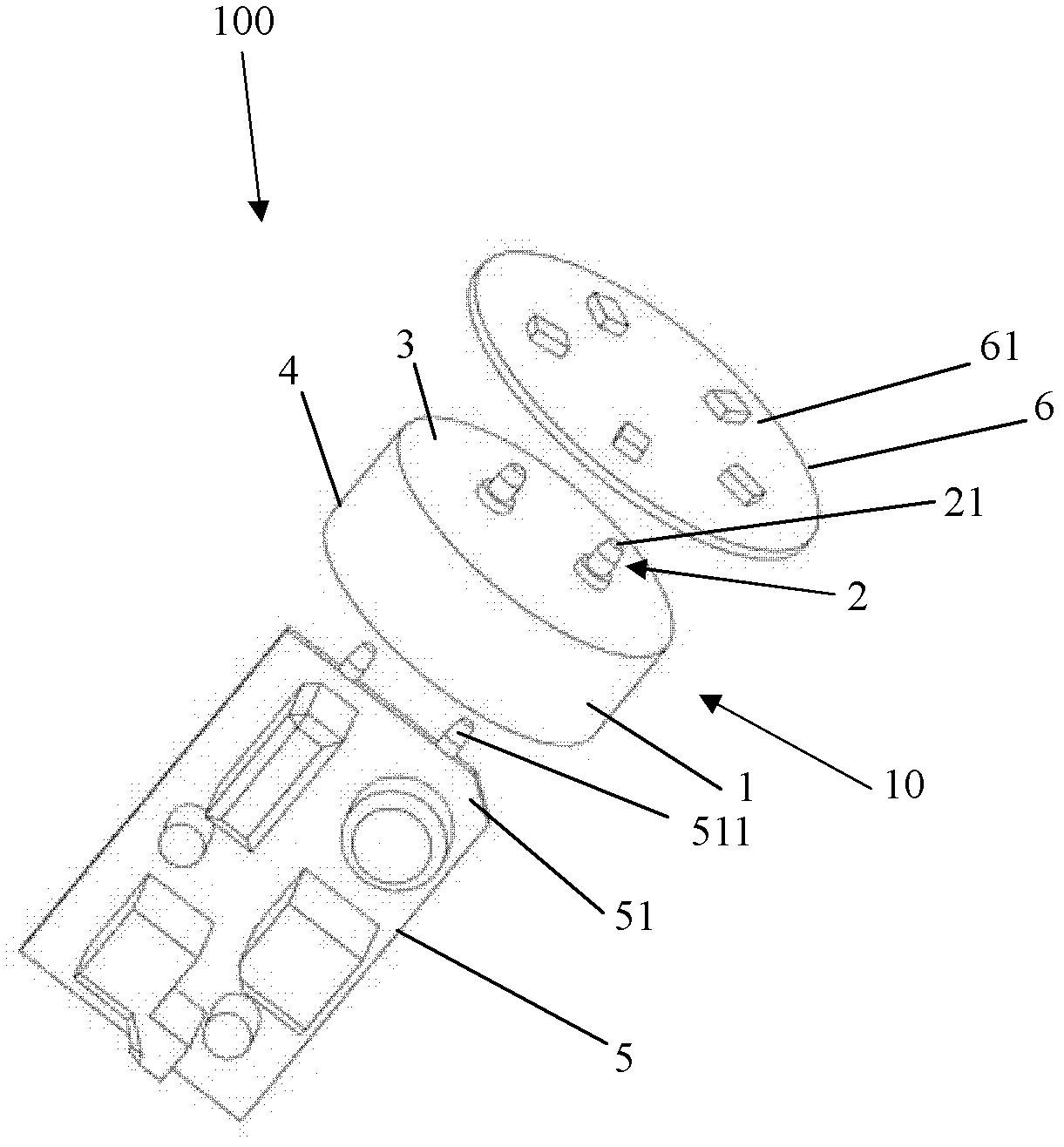
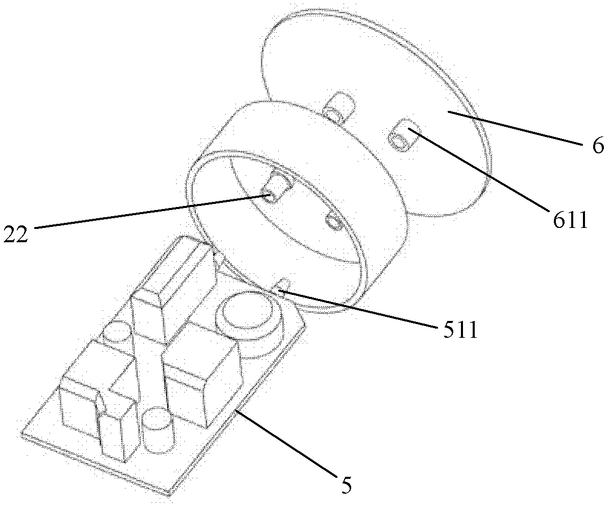
[0027] figure 1 is a perspective view of the light emitting device 100 according to the first embodiment of the present invention. figure 2 , 3 are the first and second exploded views of the light emitting device 100 according to the first embodiment of the present invention. A drive housing 10 according to the invention is shown therein.

[0028] The driver housing 10 according to the invention mainly comprises two parts: a first part 1 and a plurality of second parts 2 . The first part 1 is an electrically insulating part and the second part 2 is a conductive part. The driver housing 10 has a base 3 and a peripheral wall 4 defined by a first part 1, and a second part 2 is formed through the base 3, and the second part 2 is a pair of conductive posts separated from each other, and the conductive posts respectively pass through the base 3 extends and has contact terminals exposed on both sides of the base 3, the paired contact terminals are respectively used for positive ...


PUM


Abstract

The invention relates to a driver casing (10). The driver casing (10) is characterized by comprising a first part (1) and a second part (2); the first part (1) is made of electrical insulating material, and the second part (2) is made of conducting material; and the first part (1) and the second part (2) are formed integrally, and the second part (2) extends out of the first part (1) and serves as the electrical connecting part of the driver casing (10). The invention also relates to a luminous device and a lamp. According to the luminous device and the lamp disclosed by the invention, the manufacturing technique is simple, the cost is low, and the heat dissipation capability is remarkably improved.

Description

technical field [0001] The invention relates to a driver housing, a light emitting device and a lamp with the light emitting device. Background technique [0002] Light-emitting devices usually have relatively large heat dissipation requirements. This is because both the light engine and the driver are heat sources that generate relatively large amounts of heat. Therefore, effective heat dissipation is required to ensure the normal operation of the light-emitting device. Especially for LED light-emitting devices, the above requirements are more urgent. [0003] In light-emitting devices, some key electronic components such as the E-cap of the driver cannot withstand high temperatures and cannot still have a high service life at high temperatures, especially in the case of natural convection, it is difficult to pass through the driver housing. The heat is dissipated due to the poor thermal conductivity of the drive housing material. [0004] There are several solutions as fo...

Claims


Application Information

Patent Timeline
IPC IPC(8): F21V29/00F21V23/00F21S2/00F21V29/50
Inventor 迪尔克·布赫豪斯尔张宏伟胡瑾陈少屏
Owner OSRAM GMBH
Why Eureka
Try Eureka