Window voltage comparison device

A technology of window voltage comparison and voltage comparison circuit, applied in the direction of adjusting electrical variables, multiple input and output pulse circuits, instruments, etc., can solve the problems of small occupation area and small static current, and achieve small occupation circuit area and static current. Small, consistent results

Active Publication Date: 2013-07-17
BYD SEMICON CO LTD
View PDF4 Cites 11 Cited by
  • Summary
  • Abstract
  • Description
  • Claims
  • Application Information

AI Technical Summary

Problems solved by technology

[0008] In order to solve the technical problems existing in the existing window voltage comparison device composed of two comparators, the

Method used


Image

  • Window voltage comparison device
  • Window voltage comparison device
  • Window voltage comparison device

Examples


Embodiment Construction

[0018] In order to make the technical problems, technical solutions and beneficial effects solved by the present invention clearer, the present invention will be further described in detail below in conjunction with the accompanying drawings and embodiments. It should be understood that the specific embodiments described here are only used to explain the present invention, not to limit the present invention.

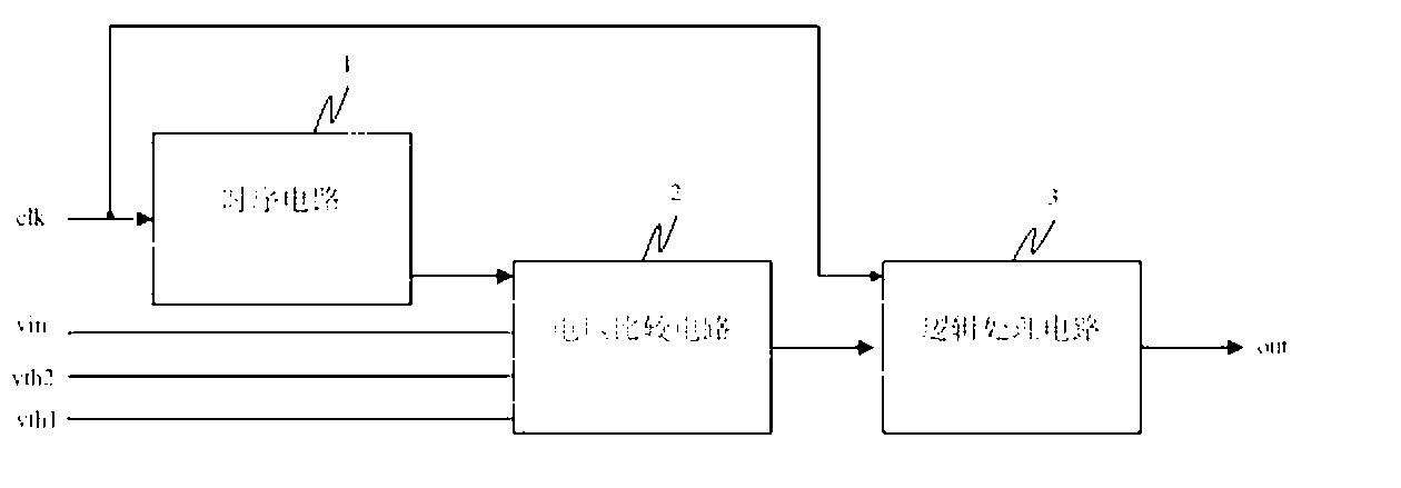
[0019] As shown in Figure 2, it is a block diagram of a window voltage comparison device according to an embodiment of the present invention, which includes:

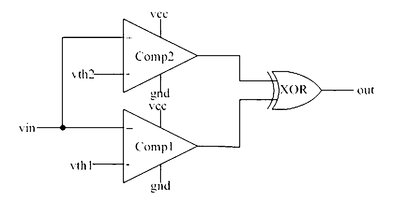
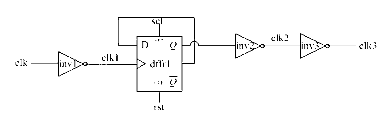
[0020] A sequential circuit 1, a voltage comparison circuit 2 and a logic processing circuit 3; the sequential circuit 1 divides the frequency of the input clock signal clk to obtain a second clock signal and a third clock signal, and outputs the second clock signal and the third clock signal To the voltage comparison circuit 2; the voltage comparison circuit 2 compares the lower limit threshold voltage vth1 or th...


PUM


Abstract

A window voltage comparison device comprises a sequential circuit, a voltage comparison circuit and a logic processing circuit. The sequential circuit performs frequency demultiplication on an input clock signal clk to obtain a second clock signal and a third clock signal and outputs the second clock signal and the third clock signal to the voltage comparison circuit; the voltage comparison circuit comprises a selector and a comparator, and the selector outputs a lower threshold voltage limit or an upper threshold voltage limit according to the control of the second clock signal and the third clock signal; the comparator compares the lower threshold voltage limit or the upper threshold voltage limit output by the selector with a voltage to be detected and outputs comparison results to the logic processing circuit; and the logic processing circuit performs logic processing on the comparison results output by the voltage comparison circuit according to triggering of the input clock signal clk and outputs processing results. The window voltage comparison device has the advantages of being small in occupied circuit area, good in consistency and low in static current.

Description

technical field [0001] The invention relates to a voltage comparison detection device, in particular to a window voltage comparison device. Background technique [0002] In integrated circuit design, especially when it comes to automatic gain control circuits, it is often necessary to judge whether the voltage of the signal falls within a certain voltage range, which requires the use of a voltage comparison detection circuit. [0003] The commonly used voltage comparison detection circuit is a window voltage comparator, as shown in Figure 1, which includes a first comparator Comp1, a second comparator Comp2 and an exclusive OR gate XOR, and the voltage vin to be detected is input into the first comparator Comp1 and the second comparator respectively. The positive input terminal of the second comparator Comp2; the negative input terminal of the first comparator Comp1 inputs the lower limit threshold voltage vth1, the negative input terminal of the second comparator Comp2 inpu...

Claims


Application Information

Patent Timeline
IPC IPC(8): H03K5/24G05F1/56
Inventor 王飞傅璟军胡文阁
Owner BYD SEMICON CO LTD
Why Eureka
Try Eureka