Inertial sensor mode tuning circuit

An inertial sensor and sensing technology, applied in the direction of acceleration measurement, instrument, TV, etc. by using inertial force, can solve stability problems and other problems

Inactive Publication Date: 2013-07-17
FAIRCHILD SEMICON CORP
View PDF5 Cites 32 Cited by
  • Summary
  • Abstract
  • Description
  • Claims
  • Application Information

AI Technical Summary

Problems solved by technology

Continuous closed-loop frequency control systems have been discussed, but such systems use considerable power due to their continuous operation and may suffer from stability problems

Method used


Image

  • Inertial sensor mode tuning circuit
  • Inertial sensor mode tuning circuit
  • Inertial sensor mode tuning circuit

Examples


example 8

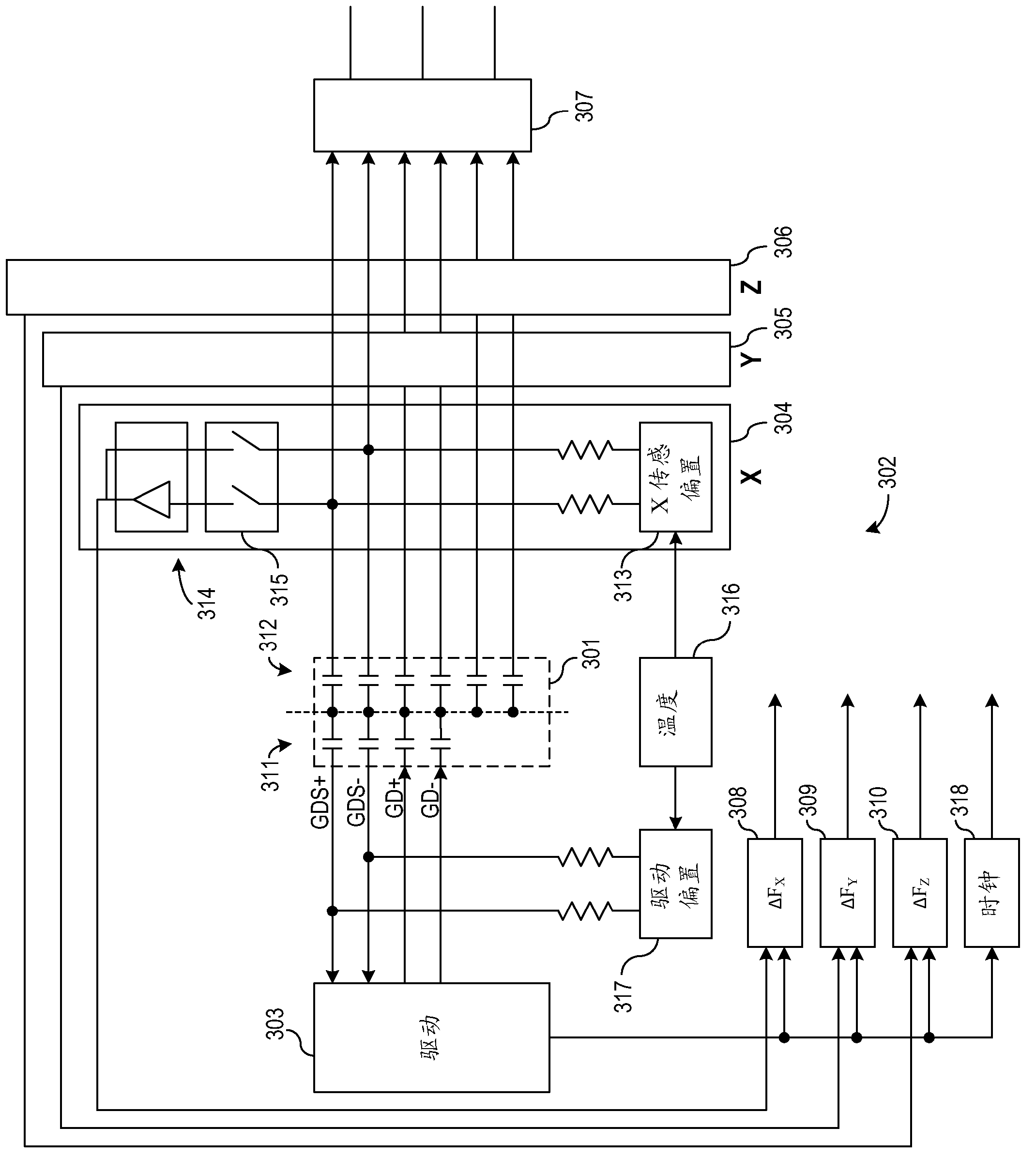
[0044] In Example 8, a method may include: selectively coupling an oscillator circuit to a sense axis of an inertial sensor; using the oscillator circuit to provide sense frequency information for the sense axis; receiving said sensing frequency information and said drive frequency information of said inertial sensor; using said frequency comparator to provide frequency difference information to a processor; receiving instructions from said processor at a programmable bias source; applying a bias voltage to the sense axis to set a sense frequency of the sense axis; and using the bias voltage to maintain a desired distance between the sense frequency and a drive frequency of the inertial sensor frequency difference.

[0045] In Example 9, selectively coupling the oscillator circuit to the sensing axis of any one or more of Examples 1-8 optionally includes actuating a switch.

[0046]In Example 10, the method of any one or more of Examples 1-9 optionally includes: selectively c...


PUM


Abstract

This document discusses, among other things, an mode matching circuit for a inertial sensor including an oscillator circuit configured to selectively couple to a sense axis of an inertial sensor and to provide sense frequency information of the sense axis, a frequency comparator configured to receive the sense frequency information of the sense axis and drive frequency information of the inertial sensor, and to provide frequency difference information to a processor, and a programmable bias source configured to apply a bias voltage to the sense axis to set a sense frequency of the sense axis in response to a command from the processor, and to maintain a desired frequency difference between the sense frequency and a drive frequency of the inertial sensor.

Description

[0001] claim priority [0002] This application claims the benefit of priority of U.S. Provisional Patent Application 61 / 384,322 filed on September 20, 2010 (Attorney Docket No. 2921.106PRV), titled "MODE TUNING CIRCUIT FOR MICROMACHINED MULTI-AXIS INERTIAL SENSORS", This provisional application is hereby incorporated by reference in its entirety. technical field [0003] The present application relates generally to inertial sensor devices, and more specifically, to pattern matching circuits for inertial sensor devices. Background technique [0004] Inertial sensors, including microelectromechanical systems (MEMS) inertial sensors, can provide useful information about the position and motion of the sensor. Such information can be used in sports electronic devices to provide navigation information and user interface information (eg, for gaming applications). The performance of a sensor may depend in part on the sensor's sensing frequency and control drive. Continuous close...

Claims


Application Information

Patent Timeline
Patent Type & Authority Applications(China)
IPC IPC(8): G01C19/5776G01P15/097B81B7/02
CPCG01P15/08G01C19/5776G01C25/00B81B7/02G01C19/56G01P15/02
Inventor J·布雷泽克
Owner FAIRCHILD SEMICON CORP
Why Eureka
Try Eureka