Rotatable welding worktable

A technology of rotary welding and workbench, which is applied in the direction of welding equipment, auxiliary welding equipment, welding/cutting auxiliary equipment, etc., which can solve the problems of reduced welding efficiency and achieve the effects of improving reliability, improving welding efficiency, and good anti-skid performance

Inactive Publication Date: 2013-07-24
四川东方能源科技股份有限公司
View PDF9 Cites 7 Cited by
  • Summary
  • Abstract
  • Description
  • Claims
  • Application Information

AI Technical Summary

Problems solved by technology

[0005] The purpose of the present invention is to overcome the problem that when welding workpieces with many weld seams, it is necessary for the staff to continuously move the position to weld each weld seam, resulting in a decrease in welding efficiency, and to provide a rotatable welding workbench

Method used


Image

  • Rotatable welding worktable
  • Rotatable welding worktable
  • Rotatable welding worktable

Examples


Embodiment 1

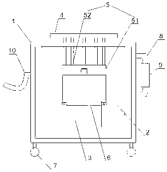
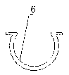
[0035] Such as figure 1 , figure 2 and image 3 As shown, the rotatable welding workbench includes a frame body 1, a welding machine fixing box 2, a motor 3, a turntable 4, a connecting device 5 and a fixing ring 6, the welding machine fixing box 2 is fixed in the frame body 1, and the fixing ring 6 is Ω type, the inner surface of the fixing ring 6 is close to the outer surface of the motor 3, the two ends of the fixing ring 6 are fixed on the welding machine fixing box 2 through bolt connection, and the output shaft of the motor 3 is connected with the turntable 4 through the connecting device 5.

[0036] The welder fixing box 2 is used to accommodate the welder. When working, the workpiece to be welded is placed on the turntable 4, and the motor 3 drives the turntable 4 to rotate, so that the staff can complete the welding of the welds on different positions on the workpiece without moving the position, which can effectively improve the welding efficiency .

[0037] The...

Embodiment 2

[0039] Such as figure 1 As shown, in this embodiment, on the basis of Embodiment 1, the connecting device 5 includes a bottom plate 51 and a connecting post 52, the bottom surface of the bottom plate 51 is connected to the output shaft of the motor 3, and the connecting post 52 is evenly arranged on the bottom of the bottom plate 51. On the upper surface, the connecting column 52 is connected with the bottom surface of the turntable 4 .

[0040] Connecting the turntable 4 and the motor 3 through the connecting device 5 of the above structure can make the turntable 4 receive a uniform force and prevent the turntable 4 from overturning under the action of a heavy workpiece.

Embodiment 3

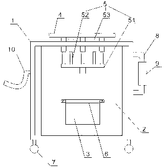
[0042] Such as figure 2 As shown, in this embodiment, on the basis of Embodiment 1, the connecting device 5 includes a bottom plate 51, a connecting column 52 and a connecting cylinder 53, the connecting cylinder 53 is evenly arranged on the bottom surface of the turntable 4, and the connecting column 52 is evenly arranged on the bottom plate 51 On the upper surface of the upper surface, the connecting column 52 is inserted into the connecting cylinder 53 , and the bottom surface of the bottom plate 51 is connected with the output shaft of the motor 3 .

[0043] The connection device 5 with the above structure is a detachable structure, which facilitates the replacement of the turntable 4 while making the turntable 4 evenly stressed. When in use, the turntable 4 can be disassembled by lifting the turntable 4, so that the turntable 4 with larger or smaller geometric dimensions can be easily replaced, so as to correspond to workpieces with different geometric dimensions.


PUM


Abstract

The invention discloses a rotatable welding worktable which comprises a frame body (1), a welding machine fixing box (2), a motor (3), a rotary table (4), a connecting device (5) and a fixing ring (6). The welding machine fixing box (2) is fixed in the frame body (1), the fixing ring (6) is Omega-shaped, the inner surface of the fixing ring (6) tightly abuts against the outer surface of the motor (3), two ends of the fixing ring (6) are connected and fixed on the welding machine fixing box (2) through bolts, and an output shaft of the motor (3) is connected with the rotary table (4) through the connecting device (5). The rotatable welding worktable has the advantages that the motor (3) and the rotary table (4) are arranged, the rotary table (4) is driven to rotate by the motor, workers can achieve welding at different positions on workpieces under the condition that the workers do not need to move, welding efficiency can be effectively improved, and the Omega-shaped fixing ring (6) is arranged and effectively fixes the motor (3), and the motor (3) is prevented from falling off.

Description

technical field [0001] The invention relates to an auxiliary tool for welding, in particular to a rotatable welding workbench. Background technique [0002] A welding machine is an electrical appliance that provides a power supply with certain characteristics for welding. The welding is flexible, simple, convenient, firm and reliable, and the advantages of high weld strength after welding are widely used in various industrial fields. [0003] At present, welding is carried out on a fixed station. When welding some workpieces with many welds and complex structures, it is necessary for the staff to continuously move the position so as to weld each weld. In some workshops with complex construction conditions, it will be very inconvenient for the staff to constantly move their positions, and their welding efficiency will be greatly reduced due to environmental restrictions. [0004] Based on the above problems, the inventor invented a rotatable welding workbench that can effect...

Claims


Application Information

Patent Timeline
Patent Type & Authority Applications(China)
IPC IPC(8): B23K37/047B23K37/00
Inventor 王曾勇叶礼
Owner 四川东方能源科技股份有限公司
Why Eureka
Try Eureka