Crossbeam expanded joint based on dovetail groove structure

A technology of dovetail grooves and beams, which is used in large fixed members, metal processing machinery parts, maintenance and safety accessories, etc., can solve problems such as increased guide rail wear, decreased machine tool life, and changes in the accuracy of structural parts, and achieves good technical results.

Inactive Publication Date: 2013-07-24
KUNSHAN THETA MICRO
View PDF7 Cites 0 Cited by
  • Summary
  • Abstract
  • Description
  • Claims
  • Application Information

AI Technical Summary

Problems solved by technology

[0005] One of the technical problems to be solved by the present invention is the corresponding stress deformation caused by the beam expansion of the gantry machine tool in the prior art, which leads to the change of the accuracy of the structural parts or the aggravation of the wear of the guide rail, and the decrease of the service life of the machine tool. A new dovetail groove structure is provided. Beam expansion joint, which has the advantage of being able to absorb the stress and deformation of the beam caused by thermal expansion

Method used


Image

  • Crossbeam expanded joint based on dovetail groove structure
  • Crossbeam expanded joint based on dovetail groove structure
  • Crossbeam expanded joint based on dovetail groove structure

Examples


Embodiment 1

[0024] A crossbeam expansion joint based on a dovetail structure, the expansion joint is a dovetail structure, the dovetail structure is connected to the end of the crossbeam, the end of the crossbeam is connected flexibly, and the other end is fixedly connected, and the crossbeam is parallel to the crossbeam When the direction shrinks or expands, the relative movement of the dovetail groove along the parallel direction of the beam will absorb the deformation caused by the shrinkage or expansion of the beam.

[0025]

Embodiment 2

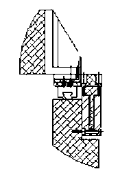
[0027] A beam expansion joint based on dovetail structure, such as figure 2 As shown, the expansion joint is a dovetail groove structure, and the dovetail groove structure is connected to the end of the beam. The end of the beam is connected flexibly, and the other end is fixedly connected. The relative movement along the parallel direction of the beam occurs, and the deformation amount caused by the contraction or expansion of the beam is absorbed. The flexible connection end adopts a flexible hinge structure, and the structural rigidity of the beam along the direction perpendicular to the length of the beam is higher than that along the length direction of the beam. When the beam expands or contracts, the beam is stable along the direction perpendicular to the beam. When the beam is heated and expanded, the dovetail grooves slide relative to each other along the length of the beam to absorb the deformation caused by the expansion of the beam. When the beam shrinks, the dov...

Embodiment 3

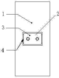
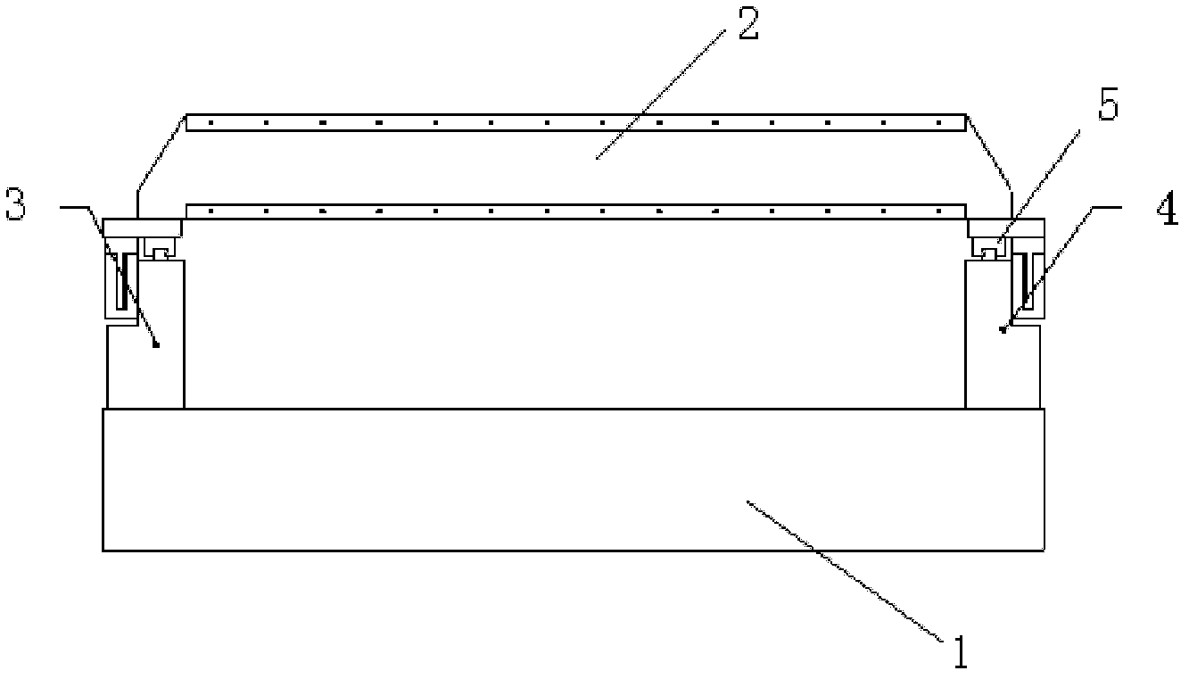
[0030] A machine tool with a gantry structure, such as figure 1 As shown, it includes a base, a beam, a left column, and a right column. The beam has an expansion joint, and the expansion joint is a dovetail groove structure. The dovetail groove structure is connected to the end of the beam. Fixed connection, when the beam shrinks or expands along the direction parallel to the beam, the dovetail groove moves relative to the beam parallel to absorb the deformation caused by the shrinkage or expansion of the beam.

[0031]


PUM


Abstract

The invention relates to a crossbeam expanded joint based on a dovetail groove structure, mainly solving the problem of stress deformation caused by the thermal expansion of a machine tool crossbeam in the prior art. The invention adopts the technical scheme that the crossbeam expanded joint based on the dovetail groove structure comprises the dovetail groove structure, one end of the crossbeam is fixedly connected, the other end of the crossbeam is flexibly connected, when the crossbeam shrinks or expands along the parallel direction of the crossbeam, the relative movement of a dovetail groove along the parallel direction of the crossbeam occurs, and the deformation amount caused by the shrinking or the expansion of the crossbeam is absorbed. According to the invention, the problem is better solved, and the crossbeam expanded joint can be applied to the industrial production of a portal structural machine tool.

Description

[0001] technical field [0002] The invention relates to a beam expansion joint based on a dovetail groove structure. Background technique [0003] In the gantry structure machine tool, the beam is a high-precision structural part. Machine tools with a gantry structure are usually larger in size and made of metal materials. Commonly used engineering materials have the problem of thermal expansion and deformation. For example, the thermal expansion coefficient of typical steel is 10×10-6m / m*℃, and the expansion coefficient of aluminum alloy is 22×10-6m / m*℃. Under the condition of Celsius, a 1-meter-long steel beam expands by 10 microns, and a 1-meter-long aluminum alloy beam expands by 22 microns. The expansion of the beam will inevitably cause corresponding stress and deformation problems, resulting in changes in the accuracy of structural parts or increased wear and tear of guide rails, and a decrease in service life. In order to solve this problem, a beam expansion join...

Claims


Application Information

Patent Timeline
IPC IPC(8): B23Q1/01B23Q11/00
Inventor 魏志凌宁军程晔蒋勤丰
Owner KUNSHAN THETA MICRO
Why Eureka
Try Eureka