
Turntable type material clamping device

A turntable-type, sandwiching technology, applied in the direction of transportation and packaging, conveyor objects, etc., can solve the problems of large manpower consumption, high labor intensity, and low production efficiency, so as to reduce production costs, reduce labor intensity, and improve production efficiency. The effect of production efficiency

Active Publication Date: 2013-07-24
SUZHOU MENGCHUAN AUTOMATION TECH
View PDF7 Cites 56 Cited by
  • Summary
  • Abstract
  • Description
  • Claims
  • Application Information

AI Technical Summary

Problems solved by technology

In the prior art, the production of this type of electronic components is often completed in parts by means of manual assembly lines. For lead fuses, the production process is usually to manually cut the fuses one by one at a fixed distance, and then cut them one by one. Insert it into the tube body, then manually bend the two ends of the fuse, put the end cap into the simple pressing tooling, press the end cap on the two ends of the tube body, and then take it out and put it in one by one after the pressing is completed. In the designated container, the above-mentioned manual production method only takes up more time for the process of taking and feeding materials, which consumes a lot of manpower and reduces production efficiency. Moreover, the demand for production personnel on the entire assembly line is large, and labor High strength, difficult to manage on site, and high production cost

Method used


Image

  • Turntable type material clamping device
  • Turntable type material clamping device
  • Turntable type material clamping device

Examples


Embodiment Construction

[0021] The technical solutions of the present invention will be further described below in conjunction with the accompanying drawings and specific embodiments.

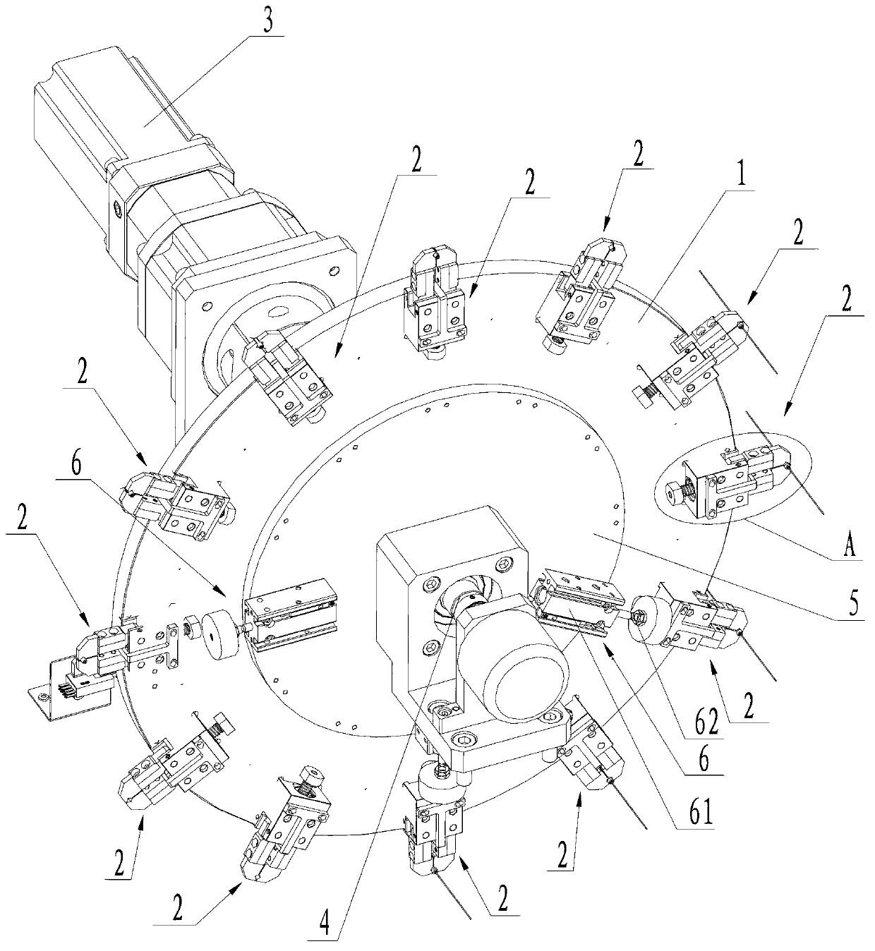
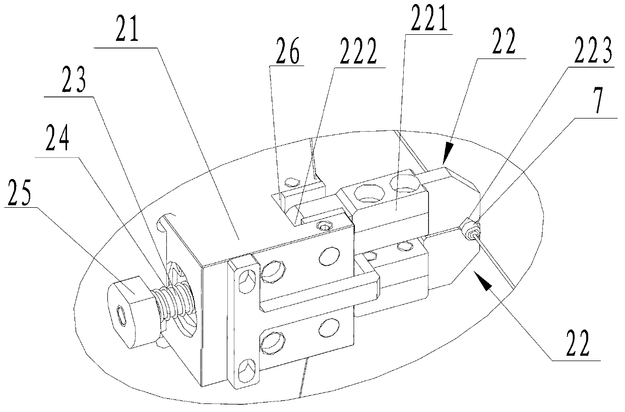
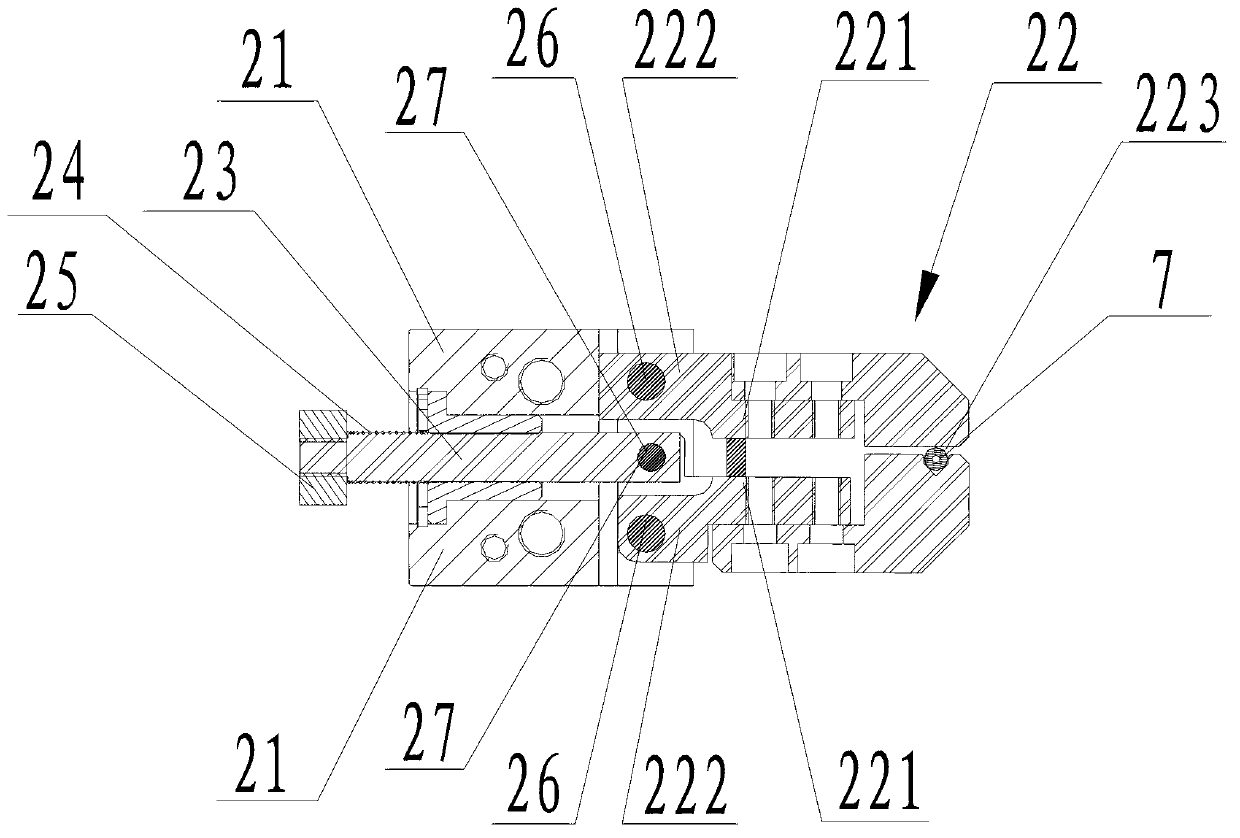
[0022] see figure 1 , figure 2 A rotary disc clamping device is shown, the clamping device includes a rotary disc 1, a rotary drive mechanism for driving the rotary disc 1 to rotate around its own axis, the center of the rotary disc 1 is pierced with a rotating shaft 4, and the rotation The shaft 4 is set to rotate synchronously with the rotary disc 1, and the rotary drive mechanism can use a servo motor 3, the output shaft of the servo motor 3 is connected to the rotary shaft 4, and the rotary shaft 4 is driven to rotate by the servo motor 3 to drive the synchronous rotation of the rotary disc 1. rotate.

[0023] see figure 1 , figure 2 As shown, one side of the rotating disk 1 is provided with a plurality of clamping assemblies 2, and these multiple clamping assemblies 2 are distributed on the rotati...


PUM


Abstract

The invention discloses a turntable type material clamping device, wherein a plurality of material clamping assemblies capable of clamping materials are arranged on a rotating disc, in addition, a rotating driving mechanism is adopted for driving the rotating disc to rotate, a material clamping driving mechanism is adopted for driving the material clamping assemblies so that the material clamping assemblies can be switched between a material taking and placing work state and a material clamping work state, when the material clamping device is adopted for producing products, a station is formed at the position of each material clamping assembly, the material taking operation and the material placing operation can be automatically carried out in the production processing, meanwhile, different processing work procedures can be carried out on different stations in the production process, the production efficiency is greatly improved, the work intensity of workers is also reduced, meanwhile, the demand on production personnel on the whole flow line is greatly reduced, the management is easy, and the production cost is also greatly reduced.

Description

[0001] technical field [0002] The invention relates to a rotary disk type clamping device. [0003] Background technique [0004] Some electronic components often include multiple processes in the production process. For example, in the lead fuse, its structure generally includes a ceramic tube body, end caps, and fuses. The end caps are arranged at both ends of the tube body, and the fuse is located in the tube body and Connects between end caps at both ends of the body. In the prior art, the production of this type of electronic components is often completed in parts by means of manual assembly lines. For lead fuses, the production process is usually to manually cut the fuses one by one at a fixed distance, and then cut them one by one. Insert it into the tube body, then manually bend the two ends of the fuse, put the end cap into the simple pressing tooling, press the end cap on the two ends of the tube body, and then take it out and put it in one by one after the pr...

Claims


Application Information

Patent Timeline
IPC IPC(8): B65G47/90
Inventor 姚友福戴龙渠
Owner SUZHOU MENGCHUAN AUTOMATION TECH
Learn More