Natural gas deacidification system applied to floating type natural gas liquefaction device

A liquefaction device and natural gas technology, which is applied in the field of natural gas deacidification system, can solve the problem of high tower height, achieve the effects of increasing floor space, high absorption rate, reducing system energy consumption and operating costs

Inactive Publication Date: 2013-07-24
CHINA NAT OFFSHORE OIL CORP +1
View PDF3 Cites 3 Cited by
  • Summary
  • Abstract
  • Description
  • Claims
  • Application Information

AI Technical Summary

Problems solved by technology

[0006] 3. If the traditional process is adopted, the height of the tower is too high

Method used


Image

  • Natural gas deacidification system applied to floating type natural gas liquefaction device
  • Natural gas deacidification system applied to floating type natural gas liquefaction device
  • Natural gas deacidification system applied to floating type natural gas liquefaction device

Examples


Embodiment Construction

[0024] The present invention will be further described below in conjunction with the accompanying drawings, but the present invention is not limited to the following embodiments.

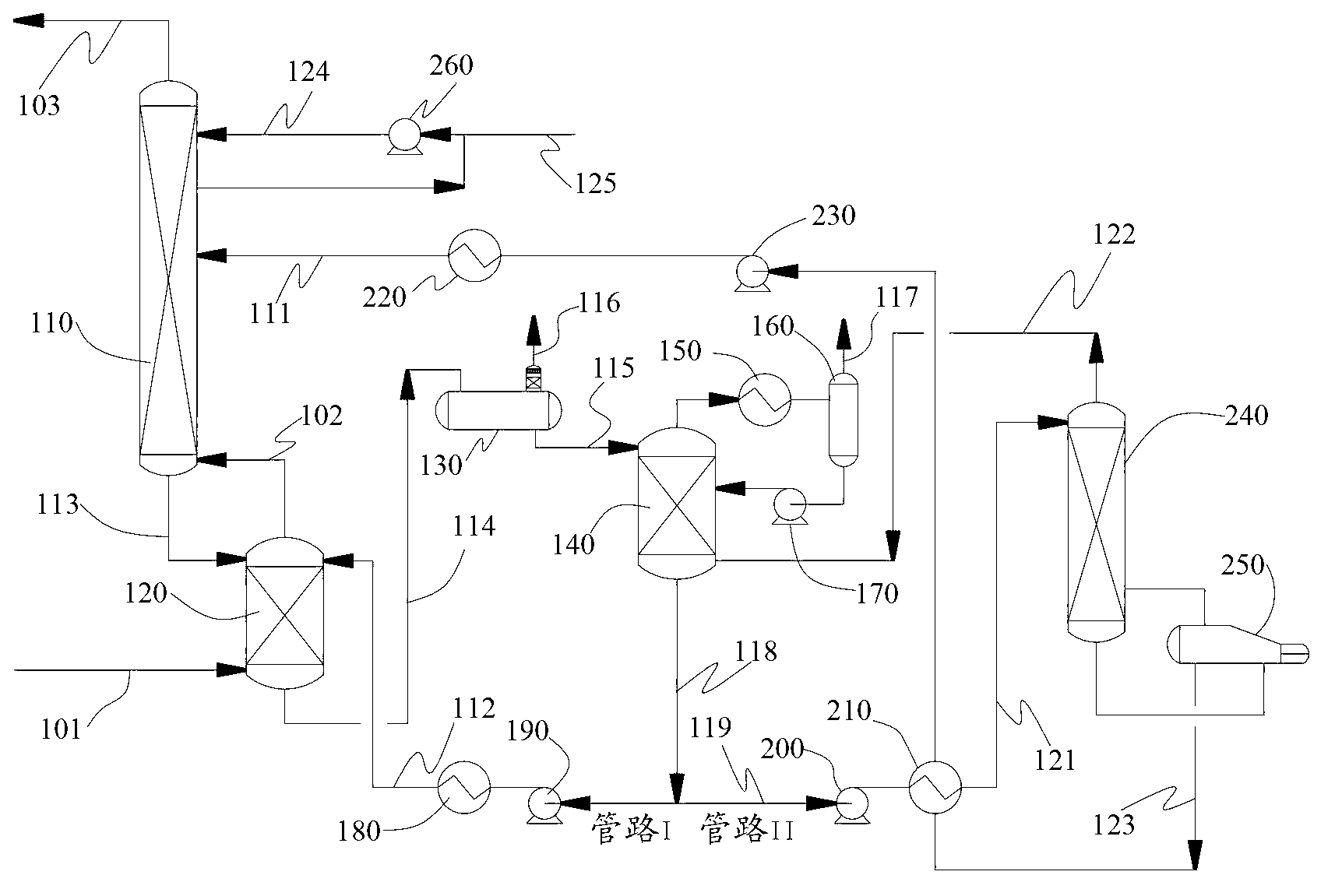
[0025] Such as figure 1 As shown, the natural gas deacidification system provided by the present invention includes a lean liquid absorption tower 110, a semi-lean liquid absorption tower 120, a lean liquid regeneration tower 140 and a semi-lean liquid regeneration tower 240; wherein the liquid phase at the bottom of the lean liquid absorption tower 110 The outlet is connected with the liquid phase inlet at the top of the semi-lean liquid absorption tower 120 , and the gas phase inlet at the bottom of the lean liquid absorption tower 110 is connected with the gas phase outlet at the top of the semi-lean liquid absorption tower 120 . The liquid phase outlet at the bottom of the semi-lean liquid absorption tower 120 communicates with the flash separator 130 for removing CO 2 , the liquid phase outlet...


PUM


Abstract

The invention discloses a natural gas deacidification system applied to a floating type natural gas liquefaction device. The natural gas deacidification system comprises a barren liquor absorption tower, a semi-barren liquor absorption tower, a barren liquor regeneration tower and a semi-barren liquor regeneration tower, wherein a liquid phase outlet of the tower bottom of the barren liquor absorption tower is communicated with a liquid phase inlet of the tower top of the semi-barren liquor absorption tower; a gas phase inlet of the tower bottom of the barren liquor absorption tower is communicated with a gas phase outlet of the tower top of the semi-barren liquor absorption tower; a liquid phase outlet of the tower bottom of the semi-barren liquor absorption tower is communicated with a flash separator; a liquid phase outlet of the flash separator is communicated with the semi-barren liquor regeneration tower; a liquid phase outlet of the tower bottom of the semi-barren liquor regeneration tower is respectively communicated with the semi-barren liquor absorption tower and the barren liquor absorption tower through a pipeline I and a pipeline II; and a heat exchanger is arranged on the pipeline II. The problem that the high-concentration CO2 cannot be deeply purified in the floating type natural gas liquefaction device is solved, the regeneration energy consumption of the absorption liquid is greatly reduced, the height of the tower is reduced, and the influence of the sea sway working conditions on the operating performance of the tower is reduced.

Description

technical field [0001] The invention relates to a natural gas deacidification system suitable for a floating natural gas liquefaction device, belonging to the technical field of natural gas purification in the field of natural gas liquefaction. Background technique [0002] The floating natural gas liquefaction device is a new type of FPSO device that integrates offshore natural gas pretreatment, liquefaction, storage and loading and unloading proposed by the marine engineering community in recent years. It will be the main means to solve the development of offshore gas fields in the future. Small size, easy to move, and high security. At present, there is no floating natural gas liquefaction unit put into operation in the world. Deep deacidification of natural gas is one of the core processes in natural gas liquefaction units, and it will face greater technical challenges in floating natural gas liquefaction units. [0003] The conventional onshore natural gas deacidifica...

Claims


Application Information

Patent Timeline
IPC IPC(8): C10L3/10
Inventor 单彤文陈杰邰晓亮尹全森曾伟平浦晖冯颉
Owner CHINA NAT OFFSHORE OIL CORP
Why Eureka
Try Eureka