Built-in type automatic pressure foot lifting mechanism of sewing machine

A presser foot lifting and built-in technology is applied in the field of built-in automatic presser foot lifting mechanism, which can solve the problems of insufficiently compact sewing machine structure, increase packaging and transportation volume, increase sewing machine cost, etc., and achieves compact structure, increased lever arm, Aesthetically pleasing effect

Active Publication Date: 2013-07-24
JACK SEWING MASCH CO LTD
View PDF9 Cites 31 Cited by
  • Summary
  • Abstract
  • Description
  • Claims
  • Application Information

AI Technical Summary

Problems solved by technology

[0007] 1. The electromagnet is bulky and expensive, which increases the cost of the sewing machine
[0008] 2. The electromagnet is placed outside, so that the structure of the sewing machine is not compact enough, which not only

Method used


Image

  • Built-in type automatic pressure foot lifting mechanism of sewing machine
  • Built-in type automatic pressure foot lifting mechanism of sewing machine
  • Built-in type automatic pressure foot lifting mechanism of sewing machine

Examples


Embodiment Construction

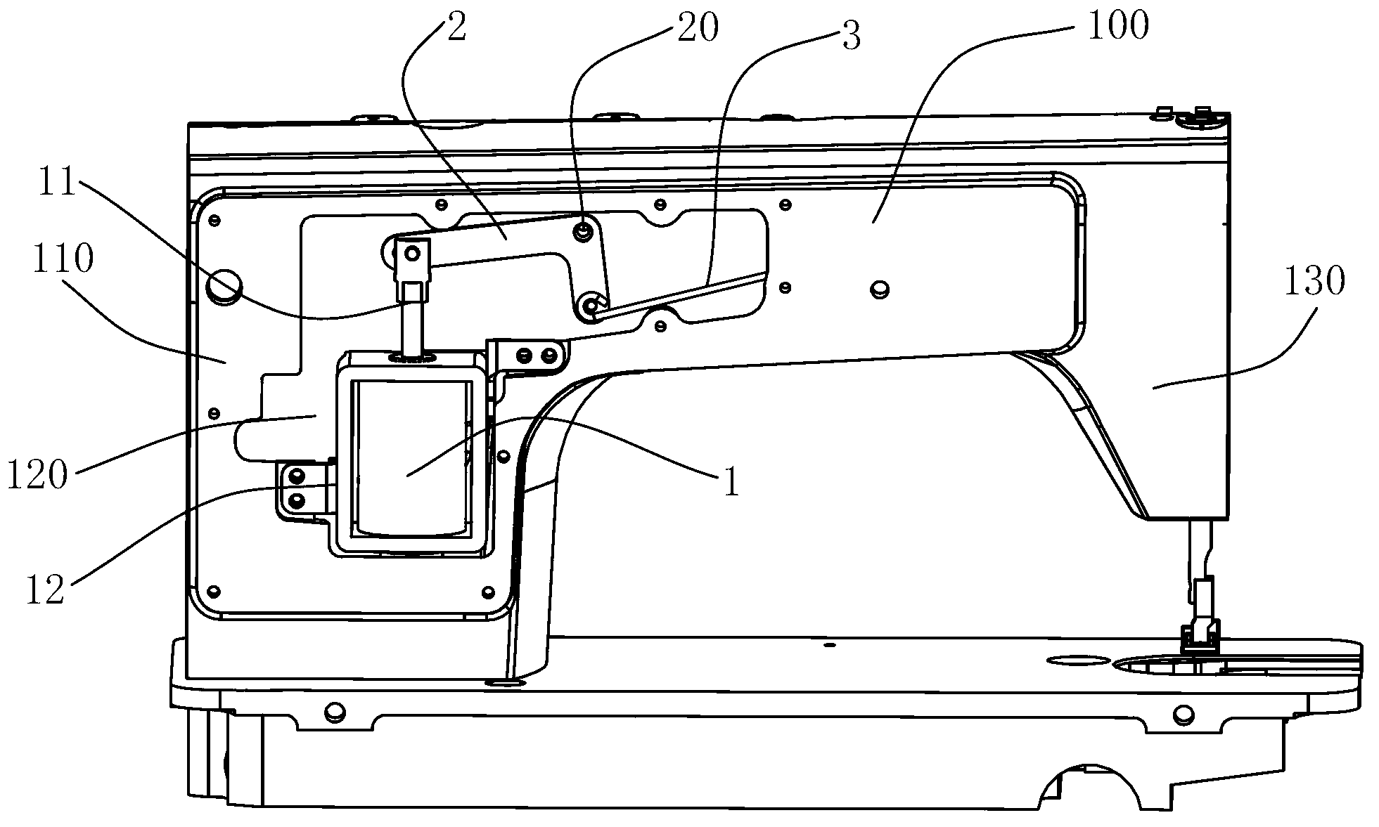
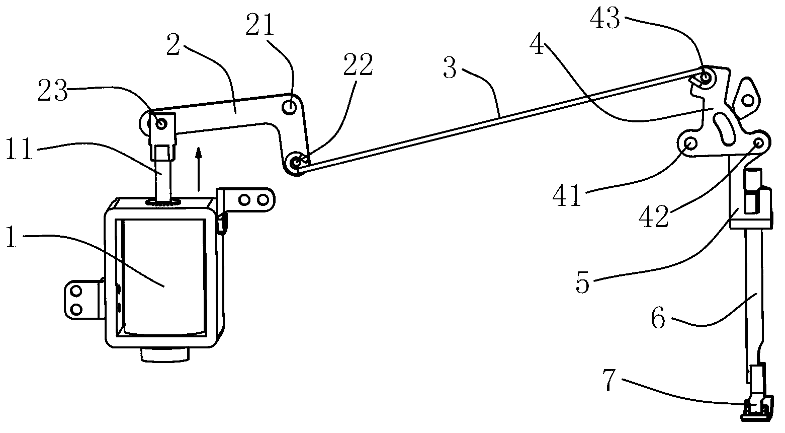
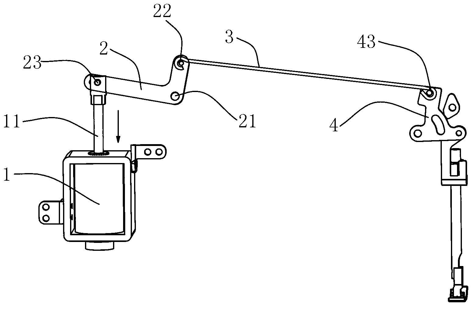
[0035] The present invention will be described in further detail below in conjunction with the accompanying drawings and specific embodiments, so that those skilled in the art can more clearly understand other advantages and effects of the present invention.

[0036] It should be noted that the structures, proportions, sizes, etc. shown in the drawings of the specification are only used to cooperate with specific implementation methods, so that those skilled in the art can understand the concept of the present invention more clearly, and are not intended to limit the scope of protection of the present invention. . Any structural modification, change in proportional relationship or size adjustment should still fall within the protection scope of the present invention, provided that it does not affect the function and purpose of the present invention. For ease of description, the relative positional relationship of each component is described according to the layout of the drawi...


PUM


Abstract

The invention discloses a built-in type automatic pressure foot lifting mechanism of a sewing machine. The built-in type automatic pressure foot lifting mechanism comprises a housing, a linear driver, a back lever, a front lever and a pull rod, wherein the housing comprises an upright column part; a cavity is formed in the upright column part; the linear driver is fixedly mounted in the cavity and comprises a drag rod which is capable of linearly moving in a reciprocating manner; a back pin hole of the back lever is hinged with one end part of the drag rod, a first front pin hole of the back lever is rotationally connected onto the housing through a pin shaft, and the distance from the back pin hole to the first front pin hole is greater than the distance from a second front pin hole to the first front pin hole; the front lever comprises three pin holes, the first pin hole is rotationally connected onto the housing through a pin shaft, and the second pin hole is hinged with a pressure foot lifting plate; and the back end of the pull rod is hinged with the second front pin hole of the back lever, and the front end of the pull rod is hinged with the third pin hole of the front lever. According to the built-in type automatic pressure foot lifting mechanism, the linear driver is arranged in the housing, so the structure of the whole mechanism is more compact, the appearance of the mechanism is more attractive, and vibration and noise produced when the automatic pressure foot lifting device works are also reduced.

Description

technical field [0001] The invention relates to an industrial sewing machine, in particular to a built-in automatic presser foot lifting mechanism for the sewing machine. Background technique [0002] At present, automatic presser foot lifting mechanisms are adopted in many industrial sewing machines to reduce the labor intensity of operators and improve labor efficiency. The existing automatic presser foot lifting mechanism is generally driven by an electromagnet, but due to the unreasonable design of the mechanism, a very large electromagnet is needed to complete the action of lifting the presser foot. [0003] For example, the Chinese utility model patent CN200820001827.4 discloses a computer direct-driven double-needle lockstitch automatic presser foot lifting mechanism, including an electromagnet, a crank, a lifting pin and a transmission part. On the rear window panel of the needle lockstitch machine head, the transmission part is rotatably installed on the other side...

Claims


Application Information

Patent Timeline
IPC IPC(8): D05B29/02
Inventor 阮积祥李创卢胜龙洪志敏
Owner JACK SEWING MASCH CO LTD
Why Eureka
Try Eureka