
Ultra-low bath ratio yarn dyeing machine water-squeezing device and squeezing method thereof

A yarn dyeing machine, ultra-low bath technology, used in textiles and papermaking, liquid/gas/vapor removal, textile material processing, etc., can solve the problems of inability to meet dyeing requirements, waste, and increased drainage time for dyed yarns

Inactive Publication Date: 2013-07-24
GUANGZHOU GAOSHENG DYEING & FINISHING EQUIPCO
View PDF8 Cites 3 Cited by
  • Summary
  • Abstract
  • Description
  • Claims
  • Application Information

AI Technical Summary

Problems solved by technology

Ordinary dyeing cannot meet higher-grade dyeing requirements due to the limitation of technological process and equipment conditions
First of all, the traditional dyeing process is long (cone yarn→water intake→add dyestuff→add sodium carbonate→add soda ash→circulate for 30min→pulse washing water→water level drainage→water intake→soaping→water level drainage→dehydrationdrying→ Winding→Completion), every link will easily cause the dyed yarn to increase the drainage time, cause the residual water of the spindle to be left for the next process to clean, etc., resulting in unnecessary loss and waste, and bring winder to the subsequent process. Difficulties in rewinding and drying

Method used


Image

  • Ultra-low bath ratio yarn dyeing machine water-squeezing device and squeezing method thereof
  • Ultra-low bath ratio yarn dyeing machine water-squeezing device and squeezing method thereof
  • Ultra-low bath ratio yarn dyeing machine water-squeezing device and squeezing method thereof

Examples


Embodiment Construction

[0068] The specific implementation of the present invention will be further described below in conjunction with the accompanying drawings, but the implementation and protection scope of the present invention are not limited thereto.

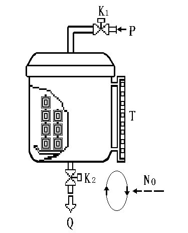
[0069] The principle of squeezing water is as figure 1 as shown, figure 1 Air pressure input pipe P; squeeze water outlet Q for draining residual water; water level display scale T; cycle number NO; compressed air squeeze water valve K 1 ;Stamped water discharge valve K 2 . Among them, the process of squeezing water and dyeing process is as follows: Dyeing process starts→water intake→add dyestuff→add sodium starch→add soda ash→circulate for 30min→pulse washing water→water level drainage→water intake→soaping→water level drainage→ Squeeze water (pressure dehydration) → complete. The invention adopts pressure dehydration to realize the dehydration of the spindle, and at the same time reduces the residual water of the spindle, which is beneficial...


PUM


Abstract

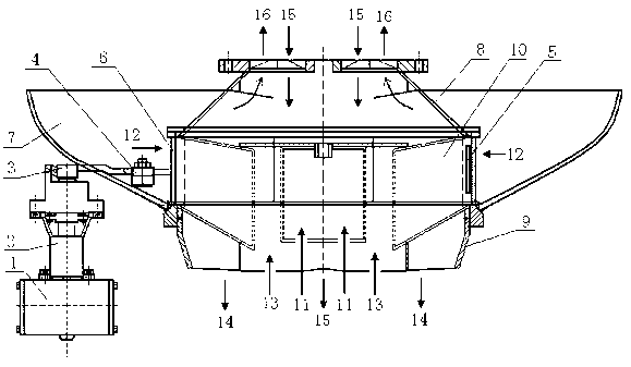
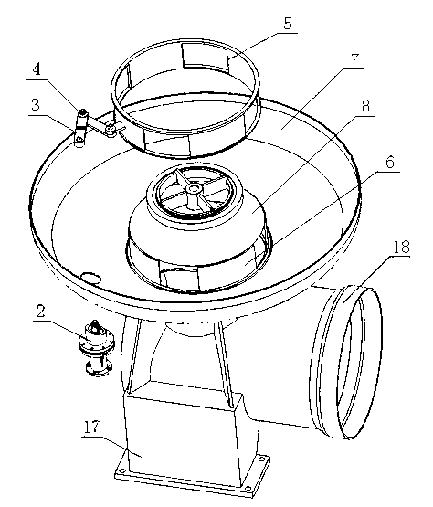
The invention discloses an ultra-low bath ratio yarn dyeing machine water-squeezing device and a squeezing method thereof. The water-squeezing device comprises a pneumatic rotating cylinder, a driving shaft, a swinging arm, a connecting rod, a semilunar valve plate, a sleeve valve ring, a compressed air water-squeezing valve and an accumulated water discharging valve. During water squeezing, the sleeve valve ring rotates to use the semilunar valve plate to block the sucking water inlet of a three-stage impeller pump and block the communication between the sucking water inlet and a main cylinder, dyeing liquid in the main cylinder and air cannot enter the three-stage impeller pump through the sucking water inlet to form a breaking state, a computer controls to add compressed air to the main cylinder, the accumulated water discharging valve is opened, a compressed air passage can only communicate with the main cylinder of a dyeing machine through a yarn disc dyeing liquid reflow inlet, and when the water inlet of the three-stage impeller pump blocks the sleeve valve ring, the dyeing liquid reflow inlet and the main cylinder are separated by a spindle, the compressed air can only be exhausted by the accumulated water discharging valve from the yarn disc dyeing liquid reflow inlet after passing through the spindle, and water is removed. The ultra-low bath ratio yarn dyeing machine water-squeezing device is simple in structure, the water using amount of the dyeing machine is not increased, the dyeing time can be shortened, and the dyeing efficiency is improved.

Description

technical field [0001] The invention relates to a water squeezing device for an ultra-low liquor ratio yarn dyeing machine, in particular to a water squeezing device and a water squeezing method for an ultra-low liquor ratio yarn dyeing machine. Background technique [0002] The water squeezing device used in the traditional cheese dyeing machine needs to increase the bath ratio of dyeing, and the cleaning water saved by the traditional water squeezing device is offset by the increased water of the traditional water squeezing device, so it cannot be popularized and used. Ordinary dyeing cannot meet higher-grade dyeing requirements due to the limitation of technological process and equipment conditions. First of all, the traditional dyeing process is long (cone yarn→water intake→add dyestuff→add sodium carbonate→add soda ash→circulate for 30min→pulse washing water→water level drainage→water intake→soaping→water level drainage→dehydrationdrying→ Winding→Completion), every li...

Claims


Application Information

Patent Timeline
IPC IPC(8): D06B15/00
Inventor 萧振林钟汉如陈晓辉廖少委
Owner GUANGZHOU GAOSHENG DYEING & FINISHING EQUIPCO
Learn More