
Rotor cutter seat component used on pavement milling machine

A technology for milling cutters and rotor cutters, which is applied in the field of rotor cutter holder components, can solve the problems that the cutter rod cannot rotate, reduce the service life of the cutter head, etc., and achieve the effect of convenient and quick disassembly, reasonable structure and guaranteed service life

Inactive Publication Date: 2013-07-24
徐州昂拓机械科技有限公司
View PDF6 Cites 2 Cited by
  • Summary
  • Abstract
  • Description
  • Claims
  • Application Information

AI Technical Summary

Problems solved by technology

When the cutter is working, the milling dust enters the inner cavity of the cutter holder through the opening groove of the elastic opening fastening sleeve assembly. As the dust increases, the dust fills the entire inner cavity of the cutter holder, and finally the cutter rod cannot rotate, causing the cutter head to Only one surface can be used to cut the road surface, which greatly reduces the service life of the cutter head

Method used


Image

  • Rotor cutter seat component used on pavement milling machine

Examples


Embodiment Construction

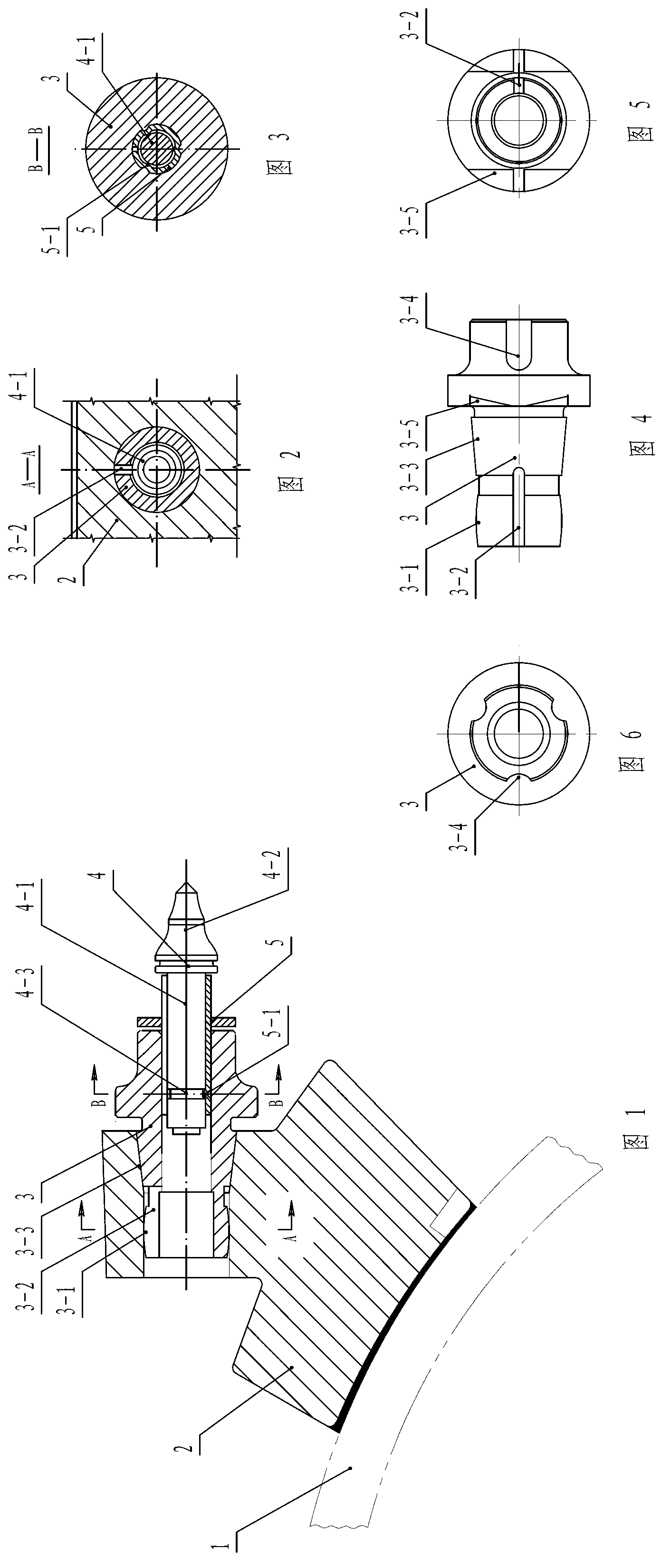
[0022] Such as Figure 1 to Figure 6 Shown: a rotor tool holder assembly used on a road milling machine, which includes: a milling cutter base 2, a cutter holder 3, an elastic opening fastening sleeve assembly 5 and a cutter 4. The cutter holder 3 is fixed on the milling cutter base 2 , and the milling cutter base 2 is welded on the milling cutter barrel 1 . Described knife cover 3 is tubular body, and the outer circle of knife cover 3 is made hook head wrench groove 3-4, open spanner surface 3-5 and conical surface 3-3; The conical hole connection of seat 2. The effect of the hook spanner groove 3-4 and the open spanner face 3-5 is to be used for easy installation and disassembly.

[0023] Described cutter 4 is made up of two parts of cutter bar 4-1 and cutter head 4-2, and described cutter bar 4-1 is installed in the inner hole of cutter holder 3 through elastic opening fastening sleeve assembly 5, and cutter bar 4 There is a gap between -1 and the hole wall of the elasti...


PUM


Abstract

The invention discloses a rotor cutter seat component used on a pavement milling machine, and relates pavement maintenance machinery. A waist drum surface is manufactured on an outer circle of a cutter sleeve and is positioned on the outer side of a conical surface; an opening slot is axially formed in the waist drum surface; the maximum diameter of the slotted waist drum surface is 2-3 mm greater than the aperture of a milling cutter base matched with the slotted waist drum surface; the cutter sleeve is fastened to the milling cutter base under the action of elastic interference of the waist drum surface; and the cutter sleeve and the milling cutter base are connected in an own elastic tensioning manner, so that the cutter sleeve and the milling cutter base are tightly combined with each other and are convenient to mount and dismount. The impact of a pavement to a cutter head or a milling rotor can be buffered; damage and infirmness to elements, which are caused by over constriction, are avoided; and dust entering an inner cavity of the cutter sleeve from a gap of an elastic opening fastening sleeve component is discharged from the rear end of the milling cutter base, so that the rotation of a cutter rod cannot be influenced, and the service life of the cutter head is guaranteed.

Description

technical field [0001] The invention relates to a road surface maintenance machine, in particular to a rotor knife seat assembly used on a road surface milling machine. Background technique [0002] Road surface milling machine is the main equipment for road maintenance. The milling rotor rotates at high speed to mill and break the damaged asphalt pavement, cement pavement and various roadbeds, and then lay new road surface. [0003] The applicant applied for and granted the patent right on January 12, 2012. The utility model "Milling Rotor with Quick Tool Change Used on Road Milling Machine" (Patent Publication No. 202416142U), consists of the base layout of the road milling machine Two sets of left and right symmetrical, two sets of helical wires with opposite direction of rotation. The inner surface of the base is connected with each other to form two groups of auger-type helical blade chains with opposite rotation direction. The cut materials are concentrated to the mill...

Claims


Application Information

Patent Timeline
IPC IPC(8): E01C23/088
Inventor 姚费左振景
Owner 徐州昂拓机械科技有限公司
Features
  • Generate Ideas
  • Intellectual Property
  • Life Sciences
  • Materials
  • Tech Scout
  • Unparalleled Data Quality
  • Higher Quality Content
  • 60% Fewer Hallucinations
Learn More