Moisture permeation and water proofing Cement grouting steel bar connecting structure of precast concrete unit

A prefabricated concrete and grouting connection technology, which is applied in the direction of building components, building structures, structural elements, etc., can solve the problems of unable to meet the needs of connection, large length and size of connecting steel bars, and high cost pressure, so as to improve connection performance and improve Effects of connection strength and length reduction

Active Publication Date: 2013-07-24
CENT RES INST OF BUILDING & CONSTR CO LTD MCC GRP +1
View PDF7 Cites 30 Cited by
  • Summary
  • Abstract
  • Description
  • Claims
  • Application Information

AI Technical Summary

Problems solved by technology

The disadvantage of this structure is that the connecting sleeve is an integral metal part, whether it is produced by precision casting or mechanical processing, its material and manufacturing costs are very high, and it will cost a lot to popularize and use it in prefabricated concrete structures. pressure
The advantage of this structure is: the metal pipe is made of ordinary metal profiles, no special processing is required, and the material cost is low. The steel bar is very long, which is inconvenient for transportation and installation, and the grouting connection joint is very long due to the metal pipe grouting cavity, and the amount of non-shrinkage cement filled is large, which is prone to defects of insufficient filling, which affects the quality of the joint connection
[0008] The disadvantages of this structure: First, the ring diameter of the ring-shaped stirrup connecting the node is much larger than the sleeve diameter of the steel sleeve grouting connection joint. The application of the structure is greatly limited; the second is that the length of the connecting steel bar is large, and the length of the steel bar inserted into the connecting structure is very long (at least 30 times the diameter of the connecting steel bar). When there are many connecting nodes on the component, the installation is very inconvenient; The amount of cement or cement mortar poured is very large, not only the work efficiency is low, but also the quality of the grouting connection is not easy to guarantee; Fourth, the indirect lap connection structure, eccentric load transmission, and complex stress state of the nodes are difficult to apply in the field of large-diameter steel bar connection , unable to meet the needs of the connection of high-rise prefabricated structural building components
The shape and size of steel bars are regulated by their product standards, and cannot be changed by grouting connections; the strength of cement mortar is determined by non-shrinkage cement-based grouting materials, and its strength has reached a very high level at present, further improving the strength of grouting materials Space is limited. Therefore, it is difficult to achieve obvious results by optimizing the existing cement grouting connection structure or improving the performance of grouting materials to shorten the length of joint grouting connection steel bars to reduce connection costs.

Method used


Image

  • Moisture permeation and water proofing Cement grouting steel bar connecting structure of precast concrete unit
  • Moisture permeation and water proofing Cement grouting steel bar connecting structure of precast concrete unit
  • Moisture permeation and water proofing Cement grouting steel bar connecting structure of precast concrete unit

Examples


Embodiment Construction

[0037] In order to better understand the shape, structure and characteristics of the present invention, preferred embodiments will be listed below and described in detail with reference to the accompanying drawings.

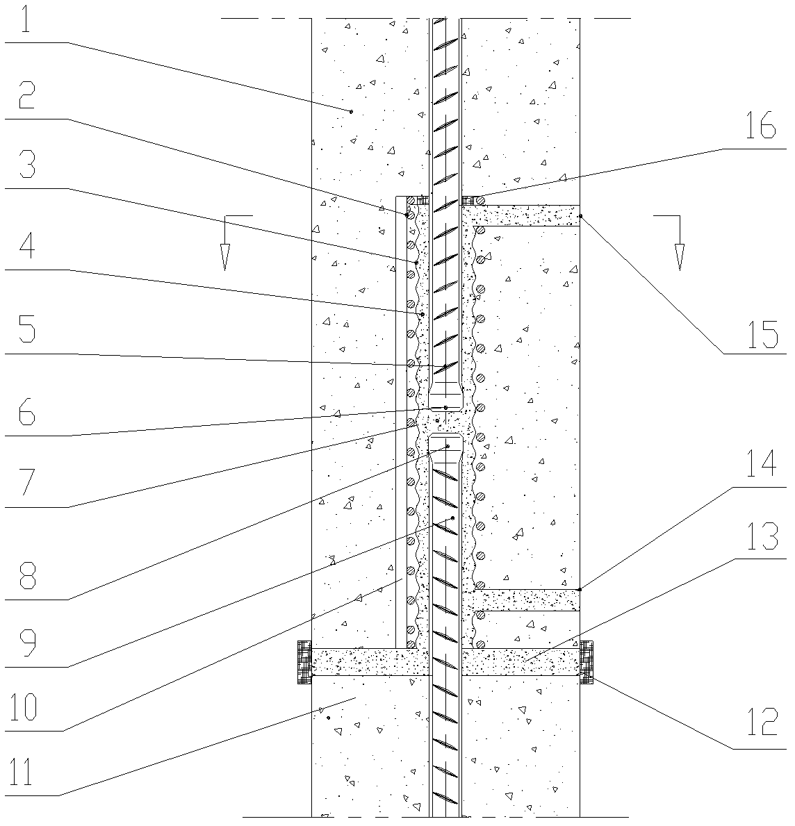
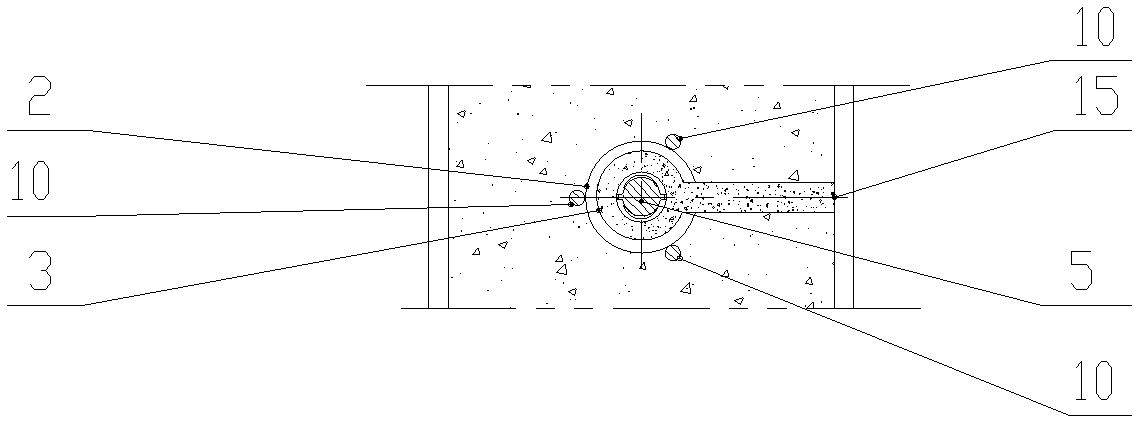
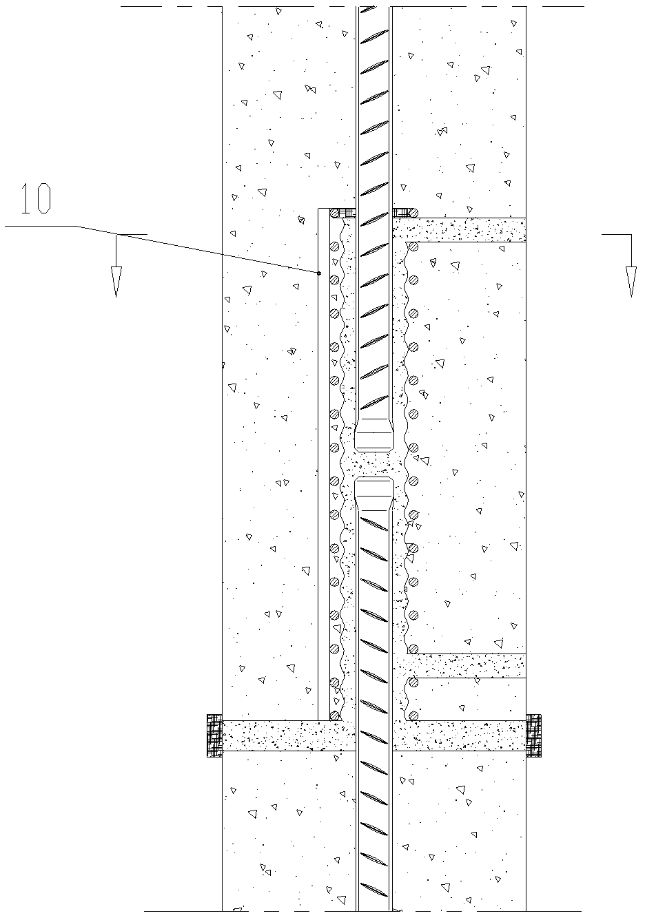
[0038] As shown in the figure, a cement grouting reinforcement connection structure includes a first component body 1 , a first connection reinforcement 5 , a second connection reinforcement 9 , ring-shaped metal stirrups 2 and non-shrinkage cement or cement mortar 4 .

[0039] There is a first connecting steel bar 5 inside the first member body 1, the connecting end of the first connecting steel bar 5 is a first anchoring head 6 whose diameter exceeds its original outer diameter by 1mm-10mm, the first member body 1 is in the first A grouting connection cavity 3 is provided at the connecting end of the connecting steel bar 5, and the connecting end of the first connecting steel bar 5 is arranged in the grouting connecting cavity, and the grouting connecting cavity...


PUM


Abstract

The invention relates to a cement grouting steel bar connecting structure of a precast concrete unit. The cement grouting steel bar connecting structure is characterized in that steel bars connected by adopting cement grouting are butted, wherein a first connecting steel bar is embedded in a first constructional element body, simultaneously the first constructional element body is provided with a grouting connection cavity, the connection end of the first connecting steel bar is arranged in the grouting connection cavity; the inner wall of the grouting connection cavity is provided with a concave-convex rough surface; an annular metal stirrup with a longitudinal connection bar is arranged at the periphery of the grouting connection cavity along the length direction of the steel bar; the connection end of a second connecting steel bar embedded in a second constructional element body is inserted in the grouting connection cavity of the first constructional element body and is opposite to the end of the first connecting steel bar; at least one of the end parts of the first connecting steel bar and the second connecting steel bar is provided with an anchoring head, the diameter of which exceeds the original external diameter; and gaps between the inner wall of the grouting connection cavity and the connecting steel bars are filled with shrinkage-free cement or cement mortar.

Description

technical field [0001] The invention relates to a steel bar connection structure applied to prefabricated concrete structure components. By using the connecting steel bars with thickened ends for cement grouting connection, the steel bar connection of prefabricated concrete components is optimized in terms of structure, material consumption and manufacturing cost. Connect to the existing cement grouting reinforcement. This structure can be applied to connect steel bars arranged vertically, horizontally or obliquely, so it can be widely used in prefabricated structural systems. Background technique [0002] In the construction of modern prefabricated concrete structures, the stressed steel bars of prefabricated components are mainly connected by sleeve cement grouting. The sleeve cement grouting steel bar joint is composed of a connecting sleeve, non-shrinking cement mortar and ribbed steel bars connected at both ends of the sleeve. The connection structure is a butt joint j...

Claims


Application Information

Patent Timeline
Patent Type & Authority Applications(China)
IPC IPC(8): E04C5/20E04B1/41
Inventor 钱冠龙郝志强刘兴亚王爱军尹华奇陈雷周雯化子龙朱清华
Owner CENT RES INST OF BUILDING & CONSTR CO LTD MCC GRP
Why Eureka
Try Eureka