Position sensor of free piston engine

A technology of piston engines and sensors, applied in free piston engines, machines/engines, using electric/magnetic devices to transmit sensing components, etc.

Inactive Publication Date: 2013-07-24
ANHUI ZHONGDING POWER
View PDF6 Cites 0 Cited by
  • Summary
  • Abstract
  • Description
  • Claims
  • Application Information

AI Technical Summary

Problems solved by technology

This patent uses a displacement sensor to determine the position of the piston assembly to increase the volume ratio of the system. Compared with this application, there are obvious differences in the device used, the installed structure and the technical effect to be achieved.

Method used


Image

  • Position sensor of free piston engine
  • Position sensor of free piston engine
  • Position sensor of free piston engine

Examples


Embodiment Construction

[0043] The present invention will be further described below in conjunction with the accompanying drawings and specific embodiments, but not as a limitation of the present invention.

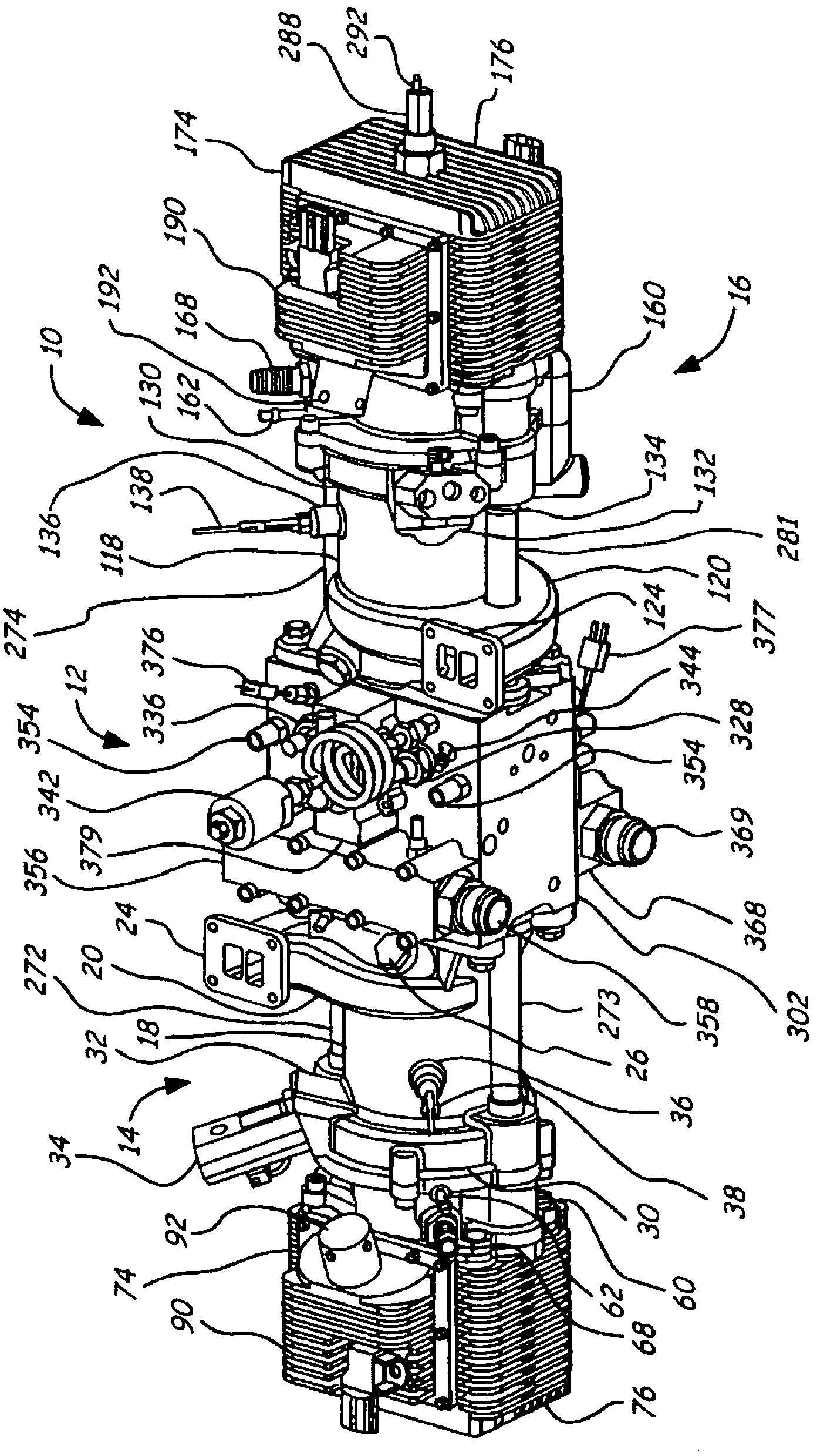
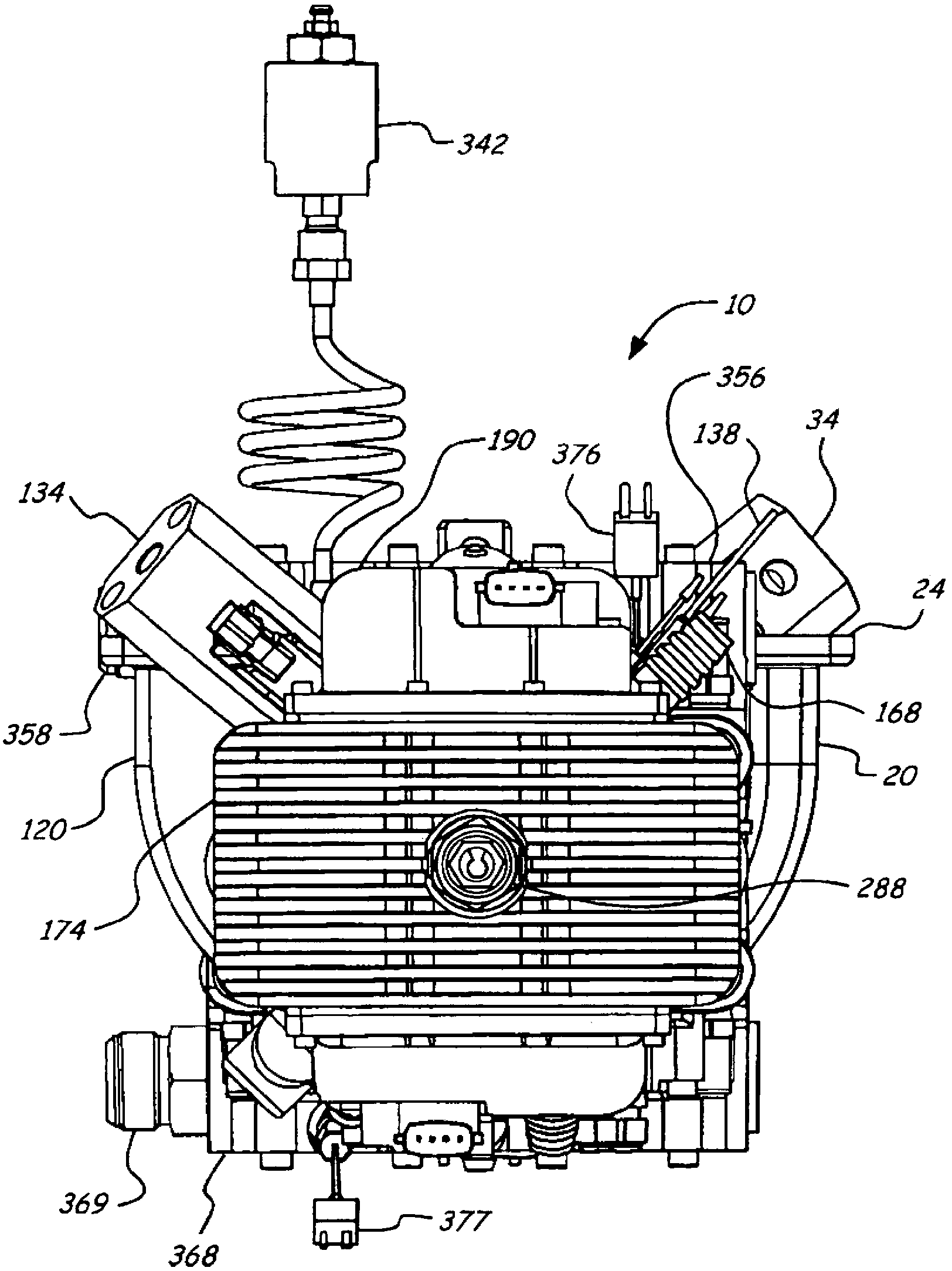
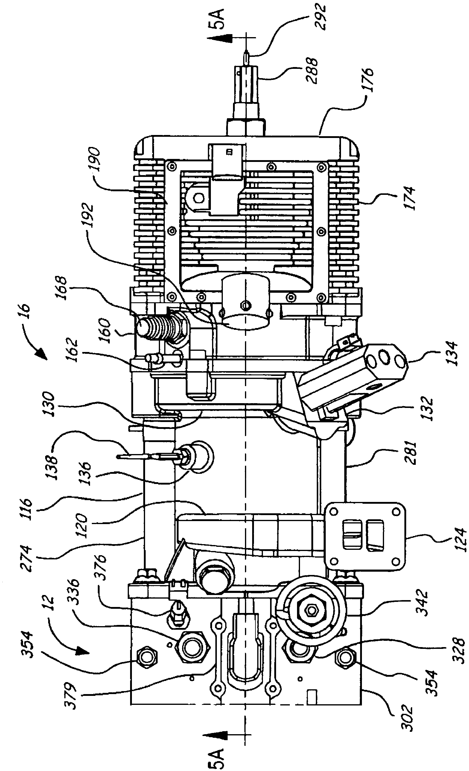
[0044] Such as Figure 1-21 A position sensor for a free piston engine of the present invention is shown, comprising a free piston engine 10 consisting of a hydraulic pump body assembly 12, a first cylinder 14, a second cylinder 16 and an internal position sensor, the first cylinder 14 being connected to a hydraulic On one side of the pump body assembly 12, the second cylinder 16 is connected to the other side of the hydraulic pump body assembly 12; the extension directions of the first cylinder 14 and the second cylinder 16 are all parallel to the axis of motion, and the first cylinder 14 and the second cylinder 16 are respectively provided with an inner piston assembly 200 and an outer piston assembly 250, and the hydraulic pump body assembly 12 is provided with a second internal position sens...


PUM


Abstract

The invention discloses a position sensor of a free piston engine. The position sensor of the free piston engine comprises the free piston engine composed of a hydraulic pump body assembly, a first cylinder and a second cylinder, wherein the first cylinder is connected with one side of the hydraulic pump body assembly, the second cylinder is connected with the other side of the hydraulic pump body assembly, an inner piston assembly is arranged in the first cylinder, an outer piston assembly is arranged in the second cylinder, and an internal position sensor body and a second internal position sensor body are arranged on the hydraulic pump body assembly. The position sensor of the free piston engine has the advantages that accurate and reliable position and speed information of the piston assemblies are provided by the position sensor bodies, the information can be obtained in the whole travel distance of each piston, interference of the motion of the piston assemblies is avoided, and the position sensor body of the inner piston assembly can be used for preventing the piston assemblies from rotating when the piston assemblies make reciprocating motion in the cylinders.

Description

technical field [0001] The invention relates to a free-piston engine, in particular to a position sensor for a free-piston engine. Background technique [0002] Generally speaking, an engine operates by the fixed mechanical motion of pistons. For example, a conventional automotive internal combustion engine consists of a crankshaft and several connecting rod components, which determine the movement of each piston in its own cylinder. This type of engine is exactly what we want, because at a given moment, the position of each piston in the working cycle is determined, and it simplifies the timing and operation of the engine. Although the efficiency of traditional types of internal combustion engines has improved greatly in recent years, due to the nature of the engine, its efficiency is still limited. Especially because the mechanical movement of the piston is fixed, it determines that the compression ratio is fixed, which leads to the limitation of its specific power. In ...

Claims


Application Information

Patent Timeline
Patent Type & Authority Applications(China)
IPC IPC(8): G01D5/12F02B71/00
Inventor 左朝凤陈新李传友夏迎松黎光福
Owner ANHUI ZHONGDING POWER
Why Eureka
Try Eureka