
A bionic inchworm-type piezoelectric rotary driver

A technology of rotary drive and bionic ruler, which is applied in the direction of generator/motor, piezoelectric effect/electrostrictive or magnetostrictive motor, electrical components, etc., which can solve the problems of insufficient processing accuracy, wear, and affecting the accuracy of the drive. , to achieve the effect of large load power output and precise driving

Inactive Publication Date: 2016-01-13
JILIN UNIV
View PDF8 Cites 2 Cited by
  • Summary
  • Abstract
  • Description
  • Claims
  • Application Information

AI Technical Summary

Problems solved by technology

[0004] The existing rotary drive device often uses simple planar contact between the driving piezoelectric stack and the drive arm, so that there will be motion interference during driving, which will affect the accuracy of the drive; moreover, most of the existing rotary drives pass through The clamping piezoelectric stack clamps the curved surface. Due to insufficient processing precision, such clamping surfaces often have insufficient contact and severe wear, which will affect the load-carrying capacity of the driver and even affect the life of the driver.

Method used


Image

  • A bionic inchworm-type piezoelectric rotary driver
  • A bionic inchworm-type piezoelectric rotary driver
  • A bionic inchworm-type piezoelectric rotary driver

Examples


Embodiment Construction

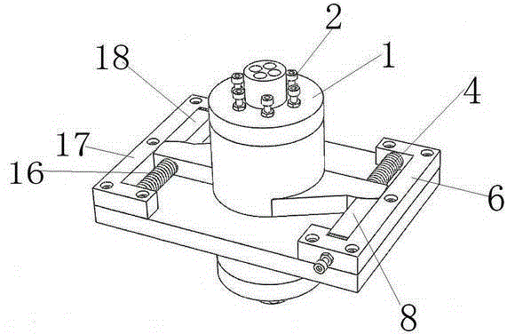
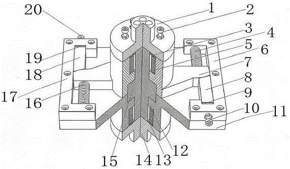
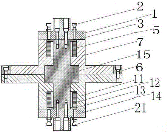
[0020] see Figure 1 to Figure 4 As shown, this embodiment is composed of the first output shaft 1, the first clamping pre-tightening bolt 2, the first clamping pre-tightening ring 3, the first return spring 4, the first annular clamping piezoelectric stack 5, the first A driving piezoelectric stack frame 6, a driving arm 7, a first driving piezoelectric stack 8, a first driving pretension block 9, a first driving pretension bolt 10, a base 11, and a second annular clamping piezoelectric stack 12. The second clamp pretension ring 13, the second output shaft 14, the drive shaft 15, the second return spring 16, the second drive piezoelectric stack frame 17, the second drive piezoelectric stack 18, the second drive preload Tightening block 19, the second driving pre-tightening bolt 20, the second clamping pre-tightening bolt 21 is composed;

[0021] The first output shaft 1 and the second output shaft 14 are respectively connected to the two ends of the drive shaft 15 by bolts, ...


PUM


Abstract

The invention discloses an inchworm-imitating piezoelectric rotary driver, which comprises output shafts, clamping and pretightening bolts, clamping and pretightening rings, restoring springs, annular clamping piezoelectric stacks, driving piezoelectric stack holders, driving arms, driving piezoelectric stacks, driving and pretightening blocks, driving and pretightening bolts and a base; the characteristic of rack-gear transmission is imitated by the driving piezoelectric stacks and the driving arms, one end of each driving piezoelectric stack is machined into the shape of the rack tooth profile, the surface of each driving arm, which is in contact with the driving piezoelectric stack, is machined into the shape of the gear involute profile, and such contact surfaces ensure that the driving units do not have motion interference, so that driving is more accurate; the annular clamping piezoelectric stacks are adopted as clamping units, rotational clamping is realized by extending both ends of each annular clamping piezoelectric stack and utilizing the static friction force between the planes, the clamping area is large, moreover, the contact between the clamping surfaces is sufficient, and high-precision and high-load output can be realized.

Description

technical field [0001] The invention relates to a bionic inchworm-type piezoelectric rotary driver, which belongs to the field of precision machining. The driver can achieve high precision and large load output, and can be widely used in ultra-precision machining machine tools, precision ultra-precision micromachining and measurement technology, nano-mechanical performance testing of material specimens, micro-electromechanical systems (MEMS), precision optics, semiconductor manufacturing , modern medicine and biogenetic engineering, aerospace, robotics, military technology and other high-end scientific and technological fields, with high scientific research value and good commercialization prospects. Background technique [0002] With the rapid development of science and technology, the requirements for product processing accuracy are getting higher and higher, especially in precision ultra-precision micromachining and measurement technology, micro-electromechanical systems ...

Claims


Application Information

Patent Timeline
Patent Type & Authority Patents(China)
IPC IPC(8): H02N2/12
Inventor 王书鹏张志辉任露泉赵宏伟
Owner JILIN UNIV
Learn More