

Circumference coupled planet synchronous rotating piston pump
A rotary piston pump, circular line technology, applied in rotary piston pumps, rotary piston machines, rotary piston engines, etc., can solve the problems of low cost, high production cost, gear wear, etc., and achieve the effect of improving life.
Pending Publication Date: 2020-02-07
徐大江
View PDF0 Cites 2 Cited by
- Summary
- Abstract
- Description
- Claims
- Application Information
AI Technical Summary
Problems solved by technology
[0002] Rotary pumps are more important pumps among various pumps, including Roots pumps, vane pumps, disc rotor pumps, gear pumps, yin and yang rotor screw pumps, etc. However, these pumps will be worn to some extent, so that their service life cannot be guaranteed. Although the blades of Roots pump, disc rotor pump, gear pump, and yin and yang rotor screw pump will not wear, both rotors participate in the compression of the fluid, and the two rotors can compress the fluid simultaneously or alternately, so the load on the synchronous gear is relatively large , the gears will have greater wear and tear, the Roots pump is the most obvious, and the overhaul time is generally only 2000 hours. Even a 5-axis machine tool is required, and the production cost is too high. This technical solution aims to propose a rotor pump with minimal or no wear, which is easy to process and low in cost. The rotor of this pump can be processed only by forming milling cutters. In the rotary piston rotor pump with circumferential line meshing, the auxiliary rotor does not do work on the fluid in the state of circumferential line meshing, so the power load of the auxiliary rotor is basically no, and the synchronous gear wears only when the concave and convex parts are coupled. Distributed to each gear, so that the life of the rotor pump is greatly improved. During the time of one revolution of the rotor, the coupling time between the blade and the groove only accounts for a small part of the total time of one revolution, and most of the time is the primary and secondary The rotor is in a circumferentially coupled state, so the wear of the synchronous gear is very small
Method used
View moreImage
Smart ImageViewing Examples

Examples
Embodiment 1
[0044] 1. Select the SU-04 piston pump, which is currently sold well in the market,
[0045] 2. Connect it to the control valve, drive it to rotate, and perform a load test on it, a seven-day full-power test. At this time, a small amount of wear occurs on the first day, and obvious wear occurs after seven days.
Embodiment 2
[0047] 1. Use the piston pump in Example 1,
[0048] 2. Connect it to the control valve, drive it to rotate clockwise, and perform a load test on it, a seven-day full-power test. At this time, there is no wear on the first day, and a small amount of wear occurs after seven days.
[0049] In summary, Embodiment 2 said that the device used has obviously improved its service life.
Login to View More PUM
 Abstract
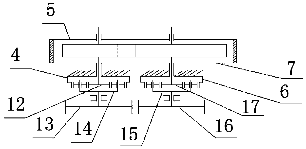
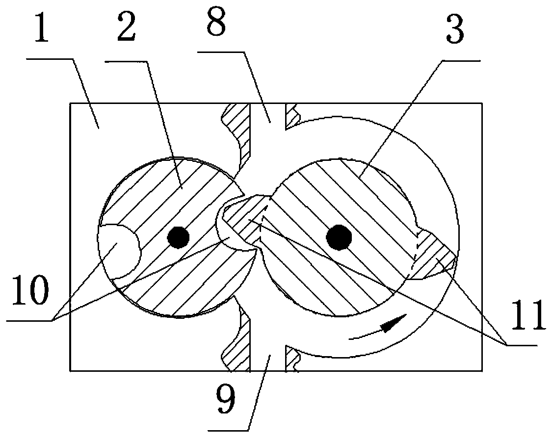
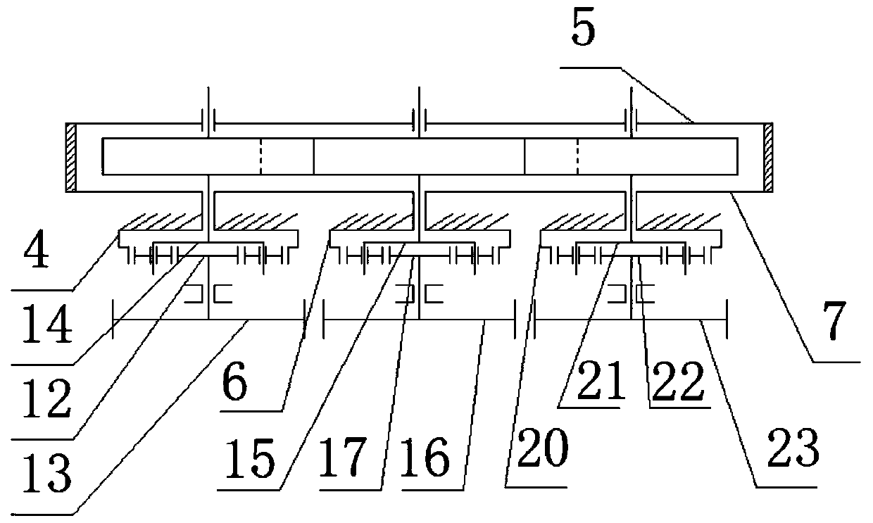
The invention discloses a circumference coupled planet synchronous rotating piston pump. The circumference coupled planet synchronous rotating piston pump comprises a pump body, a secondary rotor A, amain rotor, a front cover plate, a back cover plate, a planet synchronous gear module, an outlet and an inlet; and the main rotor is of a circular structure and provided with a main rotor blade. Through arrangement of the planet synchronous gear module, the wear is lower; a planet wheel of a planet gear continuously moves, so that the engaged positions of the gear of the planet wheel and an outergear ring during each coupling of the main and secondary rotors are different, the wear positions are different, the wear is uniformly distributed on the whole gear module, and the total wear of theplanet synchronous gear module is lower; in a non-coupling state, the main rotor and the secondary rotor are in circumference contact, the peripheral stress of the secondary rotor is zero, and the load of the synchronous gear module is zero, so that no wear is generated, and the service life is long; and the device can serve as a rotor pump, and can be reversely used as a hydraulic motor and a pneumatic motor.
Description
[0001] The invention relates to the technical field of pump production, in particular to a circular line coupling planetary synchronous rotary piston pump. Background technique [0002] Rotary pumps are more important pumps among various pumps, including Roots pumps, vane pumps, disc rotor pumps, gear pumps, yin and yang rotor screw pumps, etc. However, these pumps will be worn to some extent, so that their service life cannot be guaranteed. Although the blades of Roots pump, disc rotor pump, gear pump, and yin and yang rotor screw pump will not wear, both rotors participate in the compression of the fluid, and the two rotors can compress the fluid simultaneously or alternately, so the load on the synchronous gear is relatively large , the gears will have greater wear and tear, the Roots pump is the most obvious, and the overhaul time is generally only 2000 hours. Even a 5-axis machine tool is required, and the production cost is too high. This technical solution aims to propo...
Claims
Login to View More Application Information
Patent Timeline
 IPC IPC(8): F04C2/12F04C15/00F04C18/12F04C29/00F01C1/12F01C21/00F03C2/30F16H1/28F16H1/46
CPCF01C1/126F01C21/00F03C2/30F04C2/126F04C15/00F04C18/126F04C29/00F16H1/28F16H1/46
Inventor徐大江
Owner徐大江