Charger detection device for battery protection cascade system

A detection device and charger technology, which is applied to battery circuit devices, measurement devices, circuit devices, etc., can solve problems such as safety risks, burning out charging control transistors, cascading ICs that do not transmit charger connection information, etc., and achieve improved Safety, the effect of ensuring safety

Active Publication Date: 2013-07-24
SINO WEALTH ELECTRONICS
View PDF8 Cites 21 Cited by
  • Summary
  • Abstract
  • Description
  • Claims
  • Application Information

AI Technical Summary

Problems solved by technology

In this way, there are only two options for the overvoltage detection comparator of the cascaded IC. The first option is that the overvoltage detection comparator has no hysteresis. If the battery voltage is charged to the point where there is noise interference near the overvoltage reversal point, the overvoltage may enter and exit frequently. State, making the system working state unstable; the second option is that the overvoltage detection comparator is constant with hysteresis, when the battery voltage is charged to be greater than the overvoltage reversal point V OC , after entering the charging overvoltage state, the overvoltage comparator reversal point becomes the overvoltage detection hysteresis voltage V HYS (V HYS OC ), at this time, if the charger is unplugged and the load is connected to start discharging, as long as the battery voltage is still at V HYS Above, the cascaded IC is still in the overvoltage protection state, then the charging control transistor M CHG is off, the control transistor M will be charged by CHG The parasitic diode (Diode) discharges, and when the discharge current is large, it may burn out the charge control transistor M CHG
[0007] To sum up, the traditional battery protection cascade system either cannot detect the connection of the charger safely and reliably in all application situations; Security Risk

Method used


Image

  • Charger detection device for battery protection cascade system
  • Charger detection device for battery protection cascade system
  • Charger detection device for battery protection cascade system

Examples


Embodiment Construction

[0031] The present invention will be further described below in conjunction with specific embodiment and accompanying drawing, set forth more details in the following description so as to fully understand the present invention, but the present invention can obviously be implemented in many other ways different from this description, Those skilled in the art can make similar promotions and deductions based on actual application situations without violating the connotation of the present invention, so the content of this specific embodiment should not limit the protection scope of the present invention.

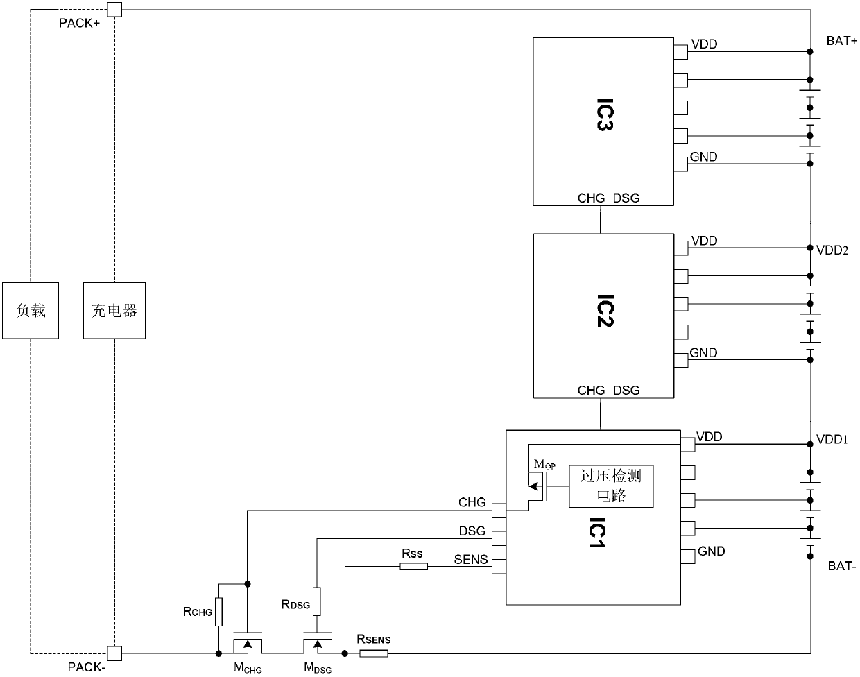
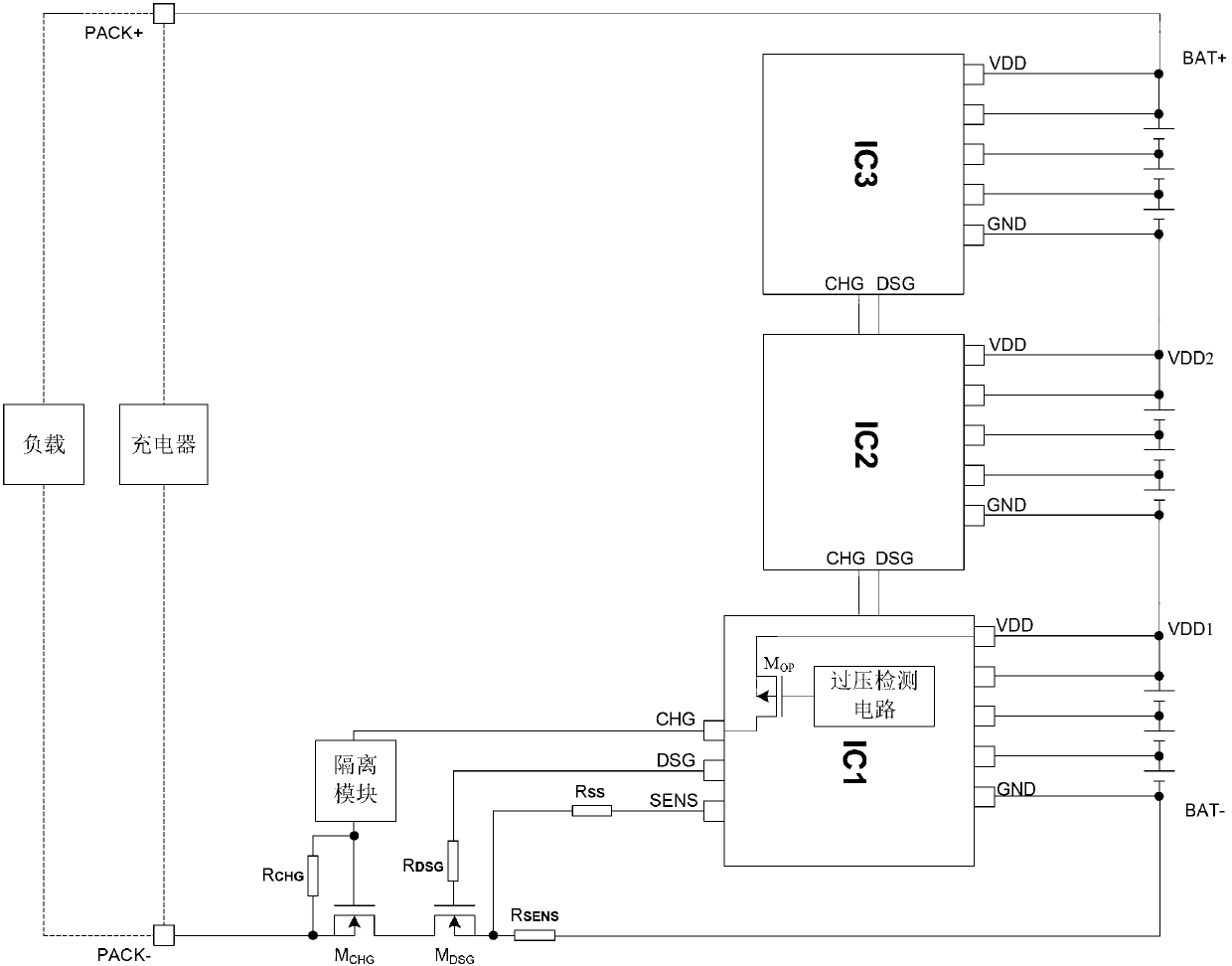
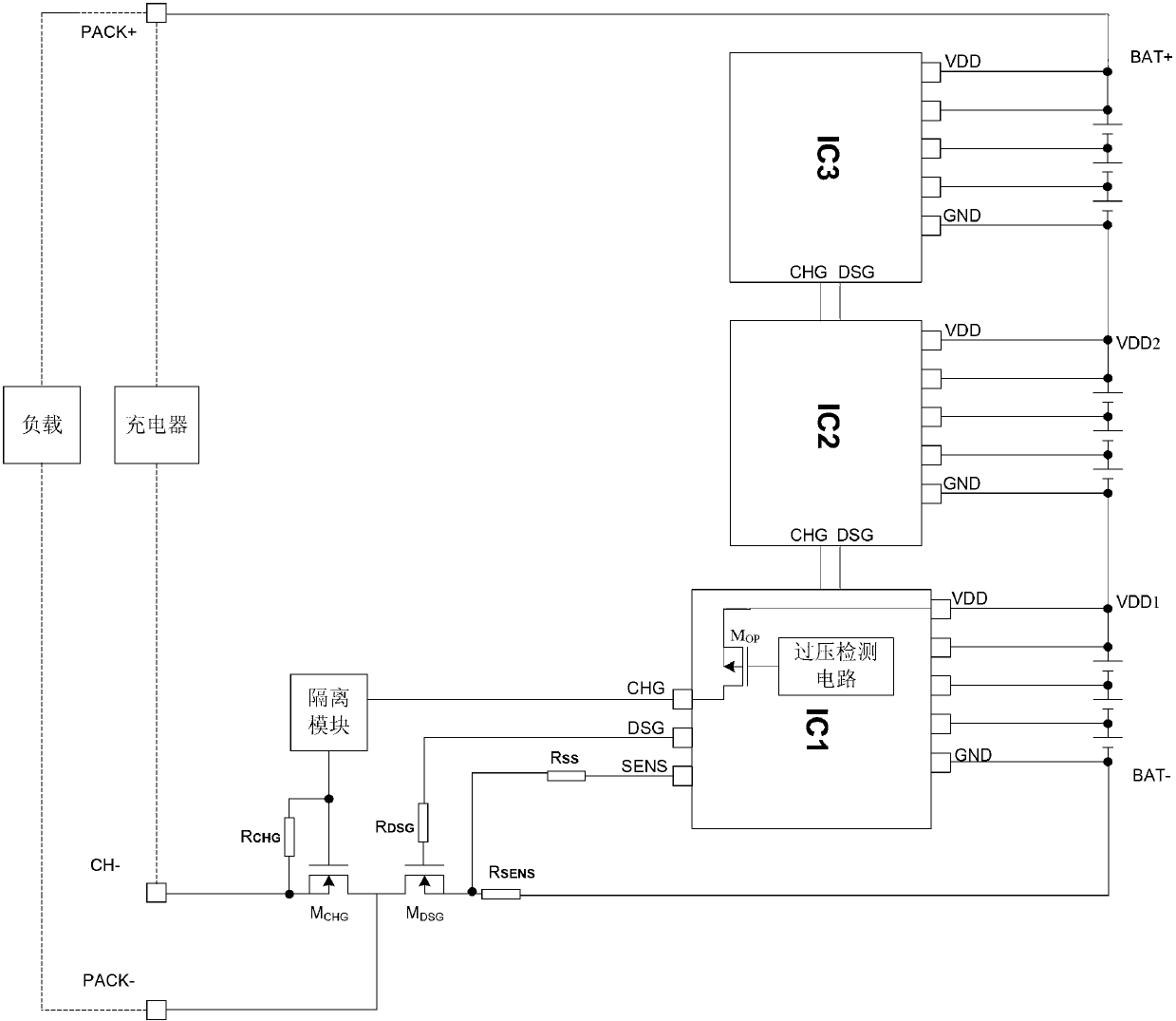
[0032] Figure 4 It is a block diagram of the charger detection device of the battery protection cascaded system according to an embodiment of the present invention, which can clearly show the charger detection method and the transmission path of the overvoltage hysteresis signal. It should be noted that this and other subsequent drawings are only examples, which are not drawn ...


PUM


Abstract

The invention provides a charger detection device for a battery protection cascade system. The charger detection device comprises N battery protection chips which are in one-to-one correspondence connection with N battery strings, wherein the first battery protection chip is a master chip and the rest battery protection chips are cascade chips; the N battery strings are connected in series, and respectively comprise M batteries, and N and M are natural numbers more than or equal to 2; each battery protection chip comprises a grounding end, a power end, a master and slave chip select signal end and a charger detection port; a connecting point of the power end of the Nth battery protection chip and the positive terminal of the Nth battery string is extracted to form the positive end of a battery pack, a connecting point of the grounding end of the master chip and the negative terminal of the first battery string is extracted to form the negative end of the battery pack, and a charger is connected between the positive end and the negative end; and the charger detection port of the master chip is connected to the negative end of the battery pack through a port resistor, the voltage of the battery pack is detected, and the connecting state of the charger is judged. The charger detection device can safely and reliably detect the connecting state of the charger, transmit an overvoltage hysteresis control signal to the cascade chips, and improve the safety of an application system.

Description

technical field [0001] The invention relates to the technical field of battery protection, in particular, the invention relates to a charger detection device for a battery protection cascade system. Background technique [0002] For the traditional battery protection cascading system, when it is applied to high-power electric tools, electric bicycles and other occasions with more than 5 strings, it is generally realized by cascading multiple ICs. figure 1 It is a block diagram of a charger detection method of a traditional lithium battery protection cascade system in the prior art. for figure 1 As shown in the traditional lithium battery protection cascade system, if a single IC (battery protection chip) can control 5 batteries, then 3 identical IC cascades can control the application system of up to 15 batteries, and the maximum operating voltage may reach 65V Above, the charger voltage will be higher than the total battery voltage. Directly control the external charging...

Claims


Application Information

Patent Timeline
Patent Type & Authority Applications(China)
IPC IPC(8): G01R31/00H02J7/00
Inventor 邢巍白胜天罗彦张树晓
Owner SINO WEALTH ELECTRONICS
Why Eureka
Try Eureka