Electric connector and electric connector component

A technology of electrical connectors and components, applied in contact parts, fixed/insulated contact components, bases/shells, etc., can solve the problem that the volume of electrical connectors cannot be compressed, increasing the difficulty of assembling plug terminals, reducing the production efficiency of electrical connectors, etc. problem, achieve the effect of reducing the number of components, simplifying the structure, and reducing the volume

Active Publication Date: 2013-07-24
CHINA AVIATION OPTICAL-ELECTRICAL TECH CO LTD
View PDF4 Cites 4 Cited by
  • Summary
  • Abstract
  • Description
  • Claims
  • Application Information

AI Technical Summary

Problems solved by technology

The plug-in terminal is fixedly assembled in the shell. In the most common structure, the plug-in terminal is often fixed in the shell by an elastic coil. Specifically, the shell is provided with a terminal mounting hole, and the hole of the terminal mounting hole There is a card slot on the wall, and the elastic coil is located in the slot. The elastic coil includes a C-shaped tension part and an elastic claw located at one end of the tension part. The tension part forms an elastic circlip structure, and the elastic claw forms a The barbed structure cooperates with one side of the retaining ring provided on the outer wall of the plug-in terminal to prevent the plug-in terminal from falling out of the shell. From the above description, we can see that the elastic coil can only prevent the plug-in terminal from falling out of the shell. Therefore, in order to completely fix the plug-in terminal, it is necessary to install other anti-rotation parts in the housing. The plug-in terminal needs elastic coils and anti-rotation parts. Coordination can be effectively fixed, that is, there are two parts used to fix the plug-in terminal, which to a certain extent forms the reason why the volume of the electrical connector cannot be compressed
In addition, when installing the elastic coil, special tooling is required for assembly, which increases the difficulty of assembling the plug-in terminal and reduces the production efficiency of the electrical connector.

Method used


Image

  • Electric connector and electric connector component
  • Electric connector and electric connector component
  • Electric connector and electric connector component

Examples


Embodiment Construction

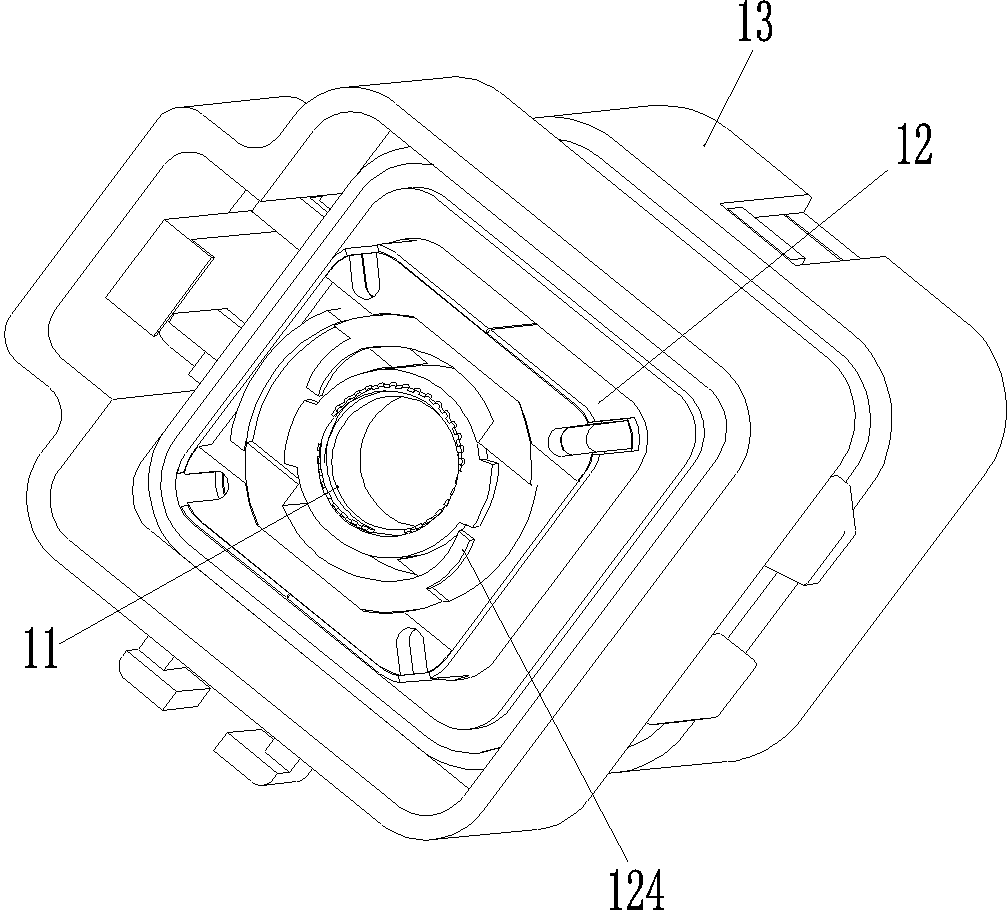
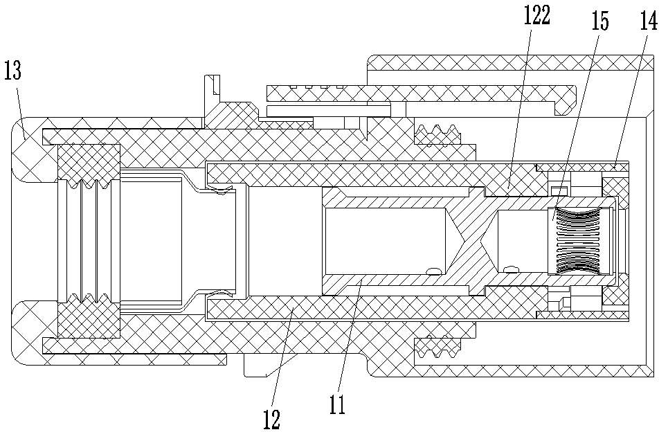
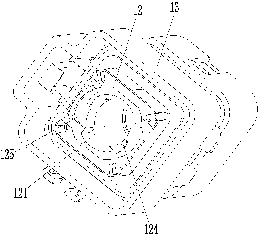
[0025] An embodiment of an electrical connector such as Figure 1-5 As shown, the electrical connector has a front end as a plug-in terminal, and includes a housing and a plug-in terminal 11 . The housing includes an inner housing 12 and an outer housing 13. The inner housing 12 is coaxially fixed and inserted in the outer housing 13. In addition, the inner housing 12 is provided with a terminal installation hole 121, and the hole wall of the terminal installation hole 121 There is a retaining ring 122 on it, and the retaining ring 122 protrudes toward the interior of the terminal installation hole 121 and has a through groove 123 through the front and back. In addition, the terminal installation hole 121 is also provided with a ratchet 124 and a stopper opposite to the ratchet 124. structure, the pawl 124 and the blocking structure are located in front of the retaining ring 122, and a bayonet structure is formed between the pawl 124 and the corresponding blocking structure to...


PUM


Abstract

The invention relates to the field of electric connectors, in particular to an electric connector and an electric connector component. The front end of the electric connector is an inserting end; the electric connector comprises a shell; an inserting terminal is matched in a terminal mounting hole of the shell; the outer circumferential surface of the inserting terminal is provided with a front limiting structure and a back limiting structure which are arranged on the front and the back; the front limiting structure is a boss arranged on the outer circumferential surface of the inserting terminal; the hole wall of the terminal mounting hole is provided with an inwards convex baffle ring; the baffle ring is provided with a through slot for the boss on the inserting terminal to pass; the distance between the front limiting structure and the back limiting structure is equal to the thickness of the baffle ring; and in addition, a pawl and a stop structure opposite to the pawl are arranged in the terminal mounting hole, are positioned in front of the baffle ring, and enclose to form a bayonet structure for preventing the inserting terminal from rotating. The size of the electric connector can be reduced correspondingly, so that the electric connector can meet the requirement on a small space, and is easy to assemble.

Description

technical field [0001] The invention relates to the field of electrical connectors, in particular to an electrical connector and an electrical connector assembly. Background technique [0002] Electrical connectors are used to connect and disconnect circuits. In recent years, with the continuous development of miniaturization, integration and high power of electrical equipment, how to reduce the size of the electrical connector as much as possible while keeping the power of the electrical connector unchanged? Its volume has become an increasingly popular research topic. [0003] At present, there are many types of electrical connectors on the market. Although their models, usage occasions and structures are different, they all contain the most core components-the housing and the plug-in terminal. The plug-in terminal is fixedly assembled in the shell. In the most common structure, the plug-in terminal is often fixed in the shell by an elastic coil. Specifically, the shell i...

Claims


Application Information

Patent Timeline
Patent Type & Authority Applications(China)
IPC IPC(8): H01R13/02H01R13/40H01R13/46
Inventor 尚超
Owner CHINA AVIATION OPTICAL-ELECTRICAL TECH CO LTD
Why Eureka
Try Eureka