Direct current transmission system based on three-pole type structure

A direct current transmission system and direct current transmission technology, applied in the direction of converting AC power input to DC power output, electrical components, power transmission AC network, etc., can solve the problem of excess reactive power, inability to operate, weak AC system or passive network, etc. problem, to achieve the effect of voltage stability

Inactive Publication Date: 2013-07-24
ZHEJIANG UNIV
View PDF3 Cites 53 Cited by
  • Summary
  • Abstract
  • Description
  • Claims
  • Application Information

AI Technical Summary

Problems solved by technology

[0005] 1. Cannot operate on weaker AC system or passive network, so it cannot transmit power to passive network or isolated load;
[0006] 2. There is a risk of commutation failure, especially in the case of a voltage drop caused by an AC system failure
Once the commutation fails, the power transmission capacity of the DC system will be cut off, causing instantaneous excess or shortage of active power in the connected AC system, resulting in deterioration of the AC and DC response characteristics, and seriously affecting the stable operation of the connected AC system;
[0007] 3. There are reactive power compensation and harmonic problems, and reactive power compensation equipment and filtering equipment need to be installed, which not only increases the cost of equipment, but also tends to cause excess reactive power during load shedding, resulting in overvoltage of the AC system;
[0008] 4. Under its special current modulation strategy, the conversion transition stage is often accompanied by changes in reactive power. Due to the slow adjustment speed of reactive power equipment, it is difficult to realize timely compensation of reactive power, which is prone to phenomena such as AC system overvoltage;
The traditional DC transmission system has a minimum DC current operation limit, which is generally about 10% of the rated value. During the current reversal period, pole 3 will run below this limit for a considerable period of time, which may easily induce DC current discontinuity and cause inductive components Overvoltage
In addition, pole 3 needs to perform locking and unlocking actions during the transition phase, which is also easy to induce overvoltage and overcurrent problems, which is not conducive to the reliable operation of the system

Method used


Image

  • Direct current transmission system based on three-pole type structure
  • Direct current transmission system based on three-pole type structure
  • Direct current transmission system based on three-pole type structure

Examples


Embodiment Construction

[0042] In order to describe the present invention more specifically, the technical solutions and related principles of the present invention will be described in detail below in conjunction with the accompanying drawings and specific embodiments.

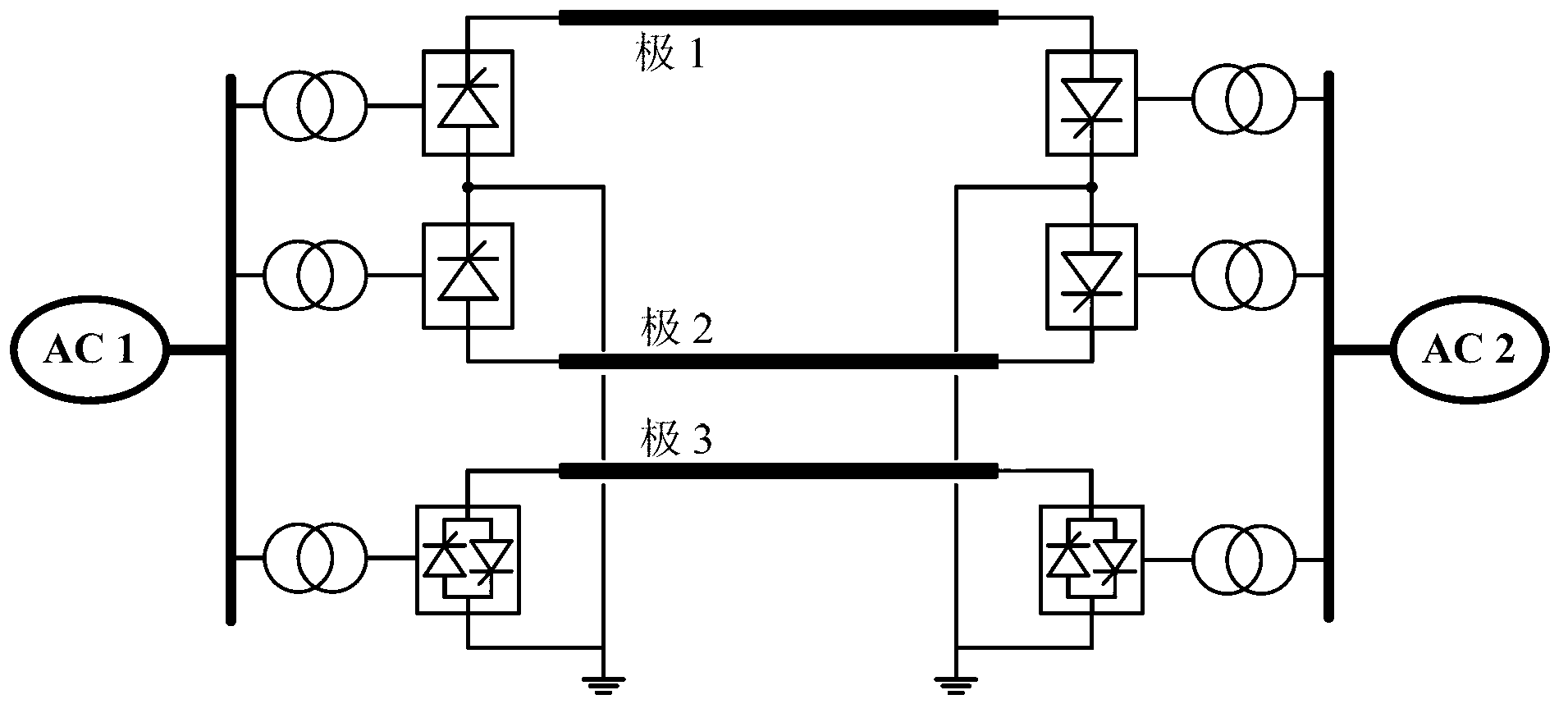
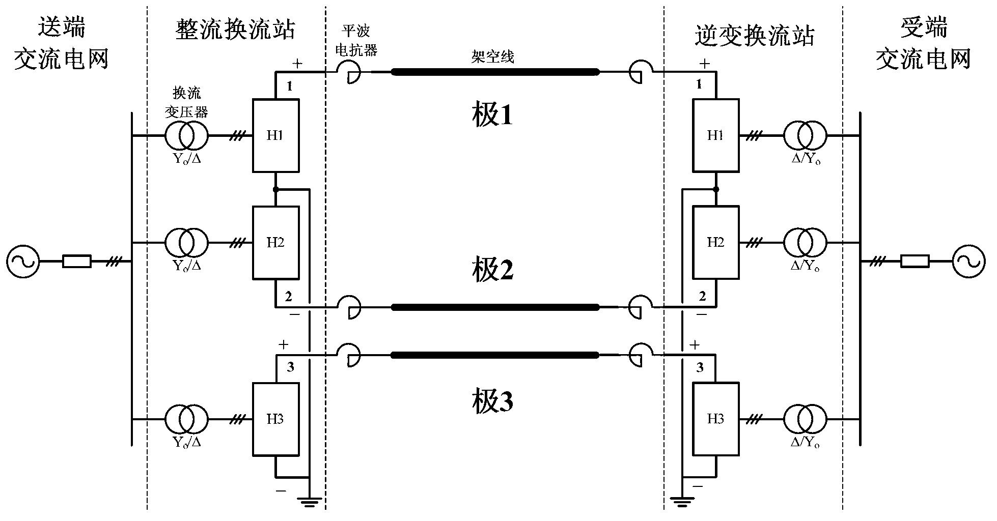
[0043] like figure 2 As shown, a DC power transmission system based on a three-pole structure includes: a rectification converter station and an inverter converter station; wherein: the rectification converter station is used to convert the three-phase AC power on the AC grid at the sending end into DC power, and the inversion converter station The flow station is used to convert the direct current into three-phase alternating current and then transmit it to the receiving end alternating current grid.

[0044] Both the rectifier station and the inverter station adopt a three-pole commutation system; the three-pole commutation system is composed of three commutation units H1-H3; the positive terminal of the DC side of the commutatio...


PUM


Abstract

The invention discloses a direct current transmission system based on a three-pole type structure. The direct current transmission system comprises a rectifying converter station and an inverting converter station, wherein the rectifying converter station and the inverting converter station respectively adopt a three-pole converter system, each three-pole converter system consists of three converter units H1, H2 and H3, each converter unit H1 and each converter unit H2 respectively adopt a modularized multilevel converter based on a CDSM (clamp dual submodule), and each converter unit H3 adopts a modularized multilevel converter based on an FBSM (full-bridge submodule). The direct current transmission system has the advantages that the CDSM and the FBSM do not need the support by an alternating current voltage source during conversion of alternating current and direction current, and the power can be supplied to a passive load; the harmonic property of the three-pole direct current is higher, the direct current latching capability is realized, meanwhile, the power and powerless decoupling controls can be realized, and the additional powerless compensation and filtering equipment are not needed; and the overvoltage phenomenon is avoided when the load shedding occurs.

Description

technical field [0001] The invention belongs to the technical field of power electronic systems, and in particular relates to a direct current transmission system based on a three-pole structure. Background technique [0002] The overall policy of my country's electric power planning is "power transmission from west to east, mutual supply between north and south, and national networking". However, with the increasing scale and complex structure of the power grid, and the interest disputes involving land acquisition issues have gradually emerged in recent years, it is more difficult to open up new line corridors on the basis of the original lines. Therefore, using the original high-voltage AC station and line grid to transform and convert it into a DC transmission project has become an idea worth exploring to solve this problem. Furthermore, for a very large-scale power grid, using DC engineering to separate it into several asynchronous subsystems can effectively reduce a se...

Claims


Application Information

Patent Timeline
Patent Type & Authority Applications(China)
IPC IPC(8): H02J3/36H02M7/219H02M7/5387
CPCY02E60/60
Inventor 徐政许烽唐庚薛英林
Owner ZHEJIANG UNIV
Why Eureka
Try Eureka