
Grid connecting system of permanent magnet synchronous wind driven generator

A wind turbine, permanent magnet synchronous technology, applied in wind power generation, control/regulation systems, electrical components, etc., can solve problems such as low grid-connected voltage, reduce heat loss, and enhance low-voltage operation capabilities.

Inactive Publication Date: 2013-07-24
TONGJI UNIV
View PDF3 Cites 17 Cited by
  • Summary
  • Abstract
  • Description
  • Claims
  • Application Information

AI Technical Summary

Problems solved by technology

[0003] Direct-drive permanent magnet synchronous wind turbines generally adopt a multi-pole low-speed structure. A typical grid-connected circuit is: fixed-point PWM converter + DC side capacitor + grid-connected PWM converter. PWM rectification technology is used in the rectification part to control The method is flexible, which is conducive to the realization of maximum torque, maximum efficiency, and minimum loss control of permanent magnet motors. The disadvantage is that the grid-connected voltage is still low, and it still needs to be boosted by a power transformer before grid-connected

Method used


Image

  • Grid connecting system of permanent magnet synchronous wind driven generator
  • Grid connecting system of permanent magnet synchronous wind driven generator
  • Grid connecting system of permanent magnet synchronous wind driven generator

Examples


Embodiment

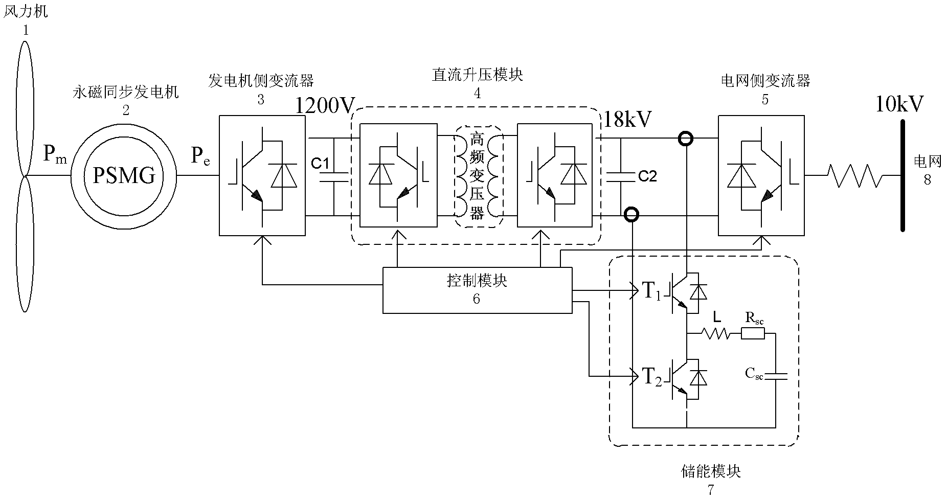
[0025] Such as figure 1 As shown, a permanent magnet synchronous wind generator grid-connected system includes a wind turbine 1, a permanent magnet synchronous generator 2, a generator-side converter 3, a DC boost module 4, a grid-side converter 5, and a control module 6 and energy storage module 7. The wind turbine 1, the permanent magnet synchronous motor 2, the generator-side converter 3, the DC boost module 4 and the grid-side converter 5 are sequentially connected to the power grid 8, and the generator-side converter 3 and the DC boost module 4 is connected in parallel with a first capacitor C1, a second capacitor C2 is connected in parallel between the DC boost module 4 and the grid-side converter 5, and the energy storage module 7 is connected in parallel between the second capacitor C2 and the grid-side converter 5 , the control module 6 is respectively connected with the generator-side converter 3 , the DC step-up module 4 , the grid-side converter 5 and the energy s...


PUM


Abstract

The invention relates to a grid connecting system of a permanent magnet synchronous wind driven generator. The grid connecting system of the permanent magnet synchronous wind driven generator comprises a wind machine, a permanent magnet synchronous generator, a generator side converter, a direct current booster module, a power grid side converter, an energy storage module and a control module. The wind machine, the permanent magnet synchronous generator, the generator side converter, the direct current booster module and the power grid side converter are connected in sequence, a first capacitor is connected between the generator side converter and the direct current booster module in parallel, a second capacitor is connected between the direct current booster module and the power grid side converter in parallel, the energy storage module is connected between the second capacitor and the power grid side converter in parallel, and the control module is respectively connected with the generator side converter, the direct current booster module, the power grid side converter and the energy storage module. Compared with the prior art, the grid connecting system of the permanent magnet synchronous wind driven generator adopts a high-frequency transformer to replace an original industrial frequency transformer to achieve high voltage grid connection, and adopts super-capacitors to store energy to enable the system to have good low-voltage operation performance.

Description

technical field [0001] The invention relates to a wind power generation grid connection system, in particular to a permanent magnet synchronous wind power generator grid connection system. Background technique [0002] The megawatt-level variable-speed and constant-frequency permanent magnet synchronous wind power generation system currently used in industry is suitable for both land wind farms and offshore wind farms. The variable speed range of the wind turbine is wide, the gearbox with a high failure rate is omitted, the reliability is good, and the generator is electrically isolated from the grid. Among them, the permanent magnet synchronous generator (permant magnetsynchronous generator, PMSG) adopts permanent magnet excitation, does not need excitation windings, brushes and slip rings, has a simple and reliable structure, and has high power generation efficiency. The use of rare earth permanent magnets can increase the air gap magnetic density, reduce the volume of th...

Claims


Application Information

Patent Timeline
IPC IPC(8): H02J3/38H02M3/335
CPCY02E10/763Y02E10/76
Inventor 张明锐王之馨徐而峰
Owner TONGJI UNIV
Learn More