Hose pipe of dust collector

A technology for vacuum cleaners and hoses, applied in the field of vacuum cleaners, can solve problems such as affecting the bending degree of hoses, and achieve the effects of improving energy efficiency, reducing noise and reducing resistance

Inactive Publication Date: 2013-07-31
SUZHOU HOWELL ELECTRIC APPLIANCES
View PDF11 Cites 1 Cited by
  • Summary
  • Abstract
  • Description
  • Claims
  • Application Information

AI Technical Summary

Problems solved by technology

[0003]1. It hinders the airflow and increases the energy loss in the process of air circulation;
[0004]2. Generates loud noise;
[0005]3. The groove is in the process of using the vacuum cleaner, and the dust will accumulate in the groove; it is inconvenient to clean
[0006]Refer to the Chinese patent "a plastic hose" with the announcement number "CN201407433Y", which discloses a On at least one of the rear surfaces, there is a rib structure protruding axially along the hose, see attached Figure 3, firstly: the two ribs do not close the U-shaped groove, and dust will accumulate in the U-shaped groove; secondly, when bending the hose , the ribs that are set opposite to each other resist the bending of the hose; even if only one rib protrudes along the axial direction and the U-shaped groove is closed, the rib top will still appear when the hose is bent The phenomenon of staying on the inner wall of the U-shaped groove
[0007] Refer to the Chinese patent "elastic ribbed tube with smooth inner wall and / or outer wall" with the announcement number "101788088A", see its attached Figure 2, 4, 5, 6, and 7 disclose a ribbed tube with a smooth inner tube surface, passing through the first and second inner walls The covering legs cover the concave part of the inner wall, but the slopes of the first and second inner wall covering legs meet when the rib tube bends inward, which still affects the bending degree of the hose

Method used


Image

  • Hose pipe of dust collector
  • Hose pipe of dust collector
  • Hose pipe of dust collector

Examples


Embodiment 1

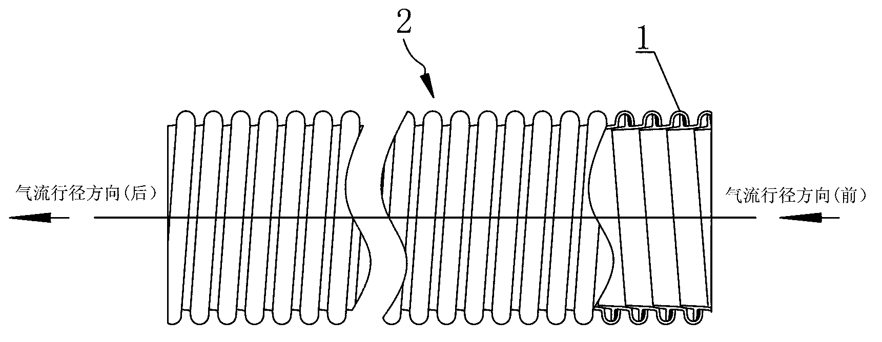
[0037] Such as figure 1 A hose for a vacuum cleaner, comprising a strip-shaped soft strip 1 extending along the length direction, the soft strip is an adhesive strip, and the strip-shaped soft strip 1 is spirally bonded to form a pipe body 2 . In this example:

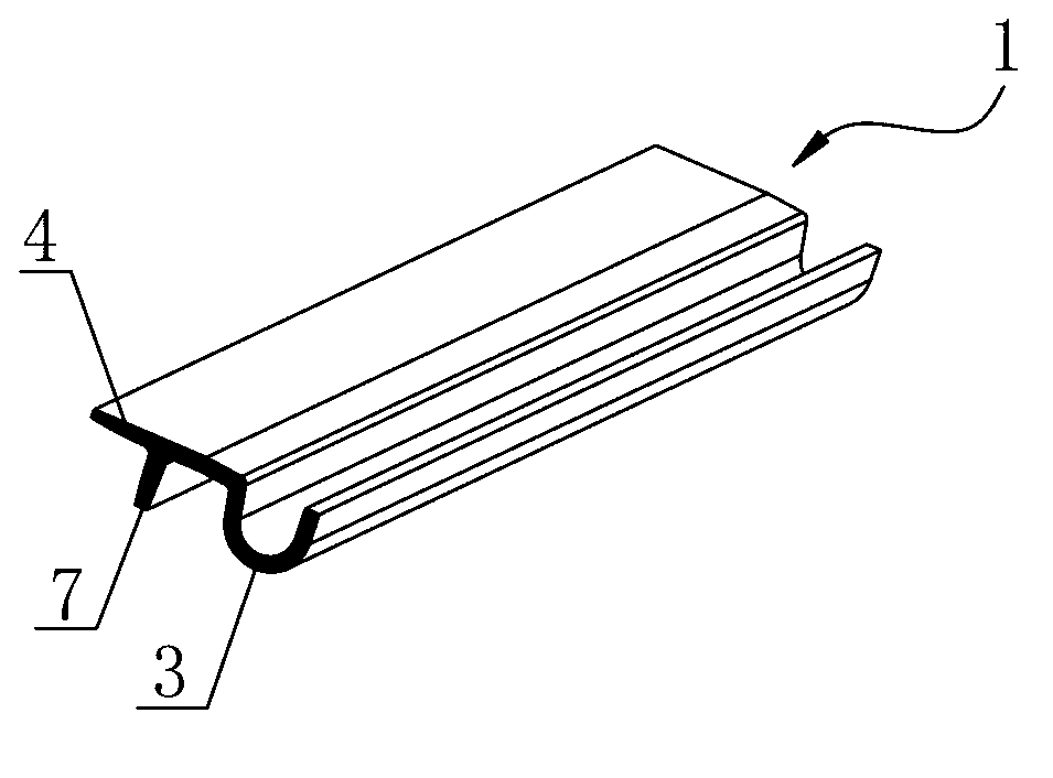
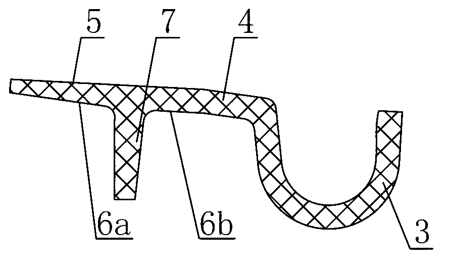
[0038] Such as figure 2 , 3 As shown: the strip-shaped flexible strip 1 includes a groove portion 3 in its width direction, an overlapping portion 4 connected to a port of the groove portion 3, the overlapping portion 4 has an inner surface 5, an outer surface 6, and the overlapping portion 4 has an inner surface 5 and an outer surface 6. The part 4 extends obliquely from one end of the groove part 3 to a direction away from one side thereof, and the outer surface 6 of the lap part 4 has a bonding part 7 extending outward, that is, the bonding part 7 connects the lap part The outer surface 6 of 4 is divided into two parts, and in this embodiment, the overlapping part 4, the groove part 3 and the bonding part ...

Embodiment 2

[0041] Such as Figure 5 A vacuum cleaner hose, comprising a strip-shaped soft strip 9 extending along the length direction, the soft strip is an adhesive strip, and the strip-shaped soft strip 9 is spirally bonded to form a pipe body 10 . In this example:

[0042] Such as Figure 6 , 7 Shown: the belt-shaped flexible strip 9 includes a groove portion 11 in its width direction, an overlapping portion 12 connected to a port of the groove portion 11, the overlapping portion 12 has an inner surface 13, an outer surface 14, and the overlapping The part 12 extends obliquely from one end of the groove part 11 towards and away from its two sides at the same time, that is, the groove part 11 divides the outer surface 14 of the lap part 12 into two; the lap part 12 moves away from the groove The outer surface 14 of the tail end of the overlapping portion 12 extending from one side of the portion 11 has a bonding portion 15 extending outward. In this embodiment, the overlapping ...


PUM


Abstract

The invention relates to a hose pipe of a dust collector. The hose pipe comprises a strip-shaped soft bars, wherein the strip-shaped soft bar is spirally adhered to form a pipe body; the strip-shaped soft bar comprises a groove part and a lap joint part connected with one port of the groove part; the lap joint part is provided with an inner surface and an outer surface; the lap joint part slantwise extends from one port of the groove part to the direction away from one side of the port; when the strip-shaped soft bar is spirally adhered to form the pipe body, the outer surface of the lap joint part of a previous ring is in lap joint on the inner surface of the lap joint part of a next ring along two adjacent rings in the front and back directions of an airflow path to shield the groove part; and the inner surface of the lap joint part of the previous ring is higher than that of the lap joint part of the next ring, so that a laminated inner surface of the pipe body is formed by the inner surface of the lap joint part. As a groove in the inner surface of the hose pipe is shielded, dust does not accumulate in the groove part; as the lap joint parts of the previous and next rings can generate relative movement, bending, stretching and compression are not affected; and as the inner surface of the hose pipe is laminated, the air flow resistance is reduced, the energy loss is decreased, and the noise is reduced.

Description

technical field [0001] The invention relates to the field of vacuum cleaners, in particular to a vacuum cleaner hose. Background technique [0002] In vacuuming equipment, hoses are mostly used, such as Figure 9 The shown vacuum cleaner hose includes a strip-shaped rubber strip 17 extending along the length direction. The strip-shaped rubber strip 17 has an inner surface 19 and an outer surface 20. The outer surface 20 of the strip 17 forms the outer tubular surface of the tubular body 18 and the inner surface 19 forms the inner tubular surface of the tubular body 18 . like Figure 11 As shown: the cross-section of the belt-shaped rubber strip 17 in the width direction is in a horizontal S shape, and the front part and the rear part of the horizontal S-shaped rubber strip 17 are bonded by glue 21 in turn. like Figure 10 As shown: there is a groove 22 in the adhesive strip 17, which also makes the inner pipe surface of the pipe body 18 have the following adverse effects ...

Claims


Application Information

Patent Timeline
Patent Type & Authority Applications(China)
IPC IPC(8): A47L9/24
Inventor 马卫宏宋刚
Owner SUZHOU HOWELL ELECTRIC APPLIANCES
Why Eureka
Try Eureka