Building ground polishing device

A polishing device and floor technology, applied in grinding/polishing safety devices, surface polishing machine tools, floor leveling/polishing machines, etc., can solve problems such as low grinding efficiency, knee and waist strain, and rising dust, and achieve strength Balanced, consistent finish, and reduced spread

Pending Publication Date: 2020-08-28
山东诚祥建设集团股份有限公司
View PDF7 Cites 0 Cited by
  • Summary
  • Abstract
  • Description
  • Claims
  • Application Information

AI Technical Summary

Problems solved by technology

[0004] Therefore, it is necessary to simply polish the floor tiles. The existing operation method is to use polishing cotton to polish the floor tiles by the worker kneeling on the ground, holding a grinder; but the dust will rise during the polishing process, which is harmful to the respiratory tract and Damage to the lungs, while prolonged kneeling operations can cause strain on the knees and lower back
And the contact area of ​​the hand-held grinding equipment is small, and the grinding efficiency is low

Method used


Image

  • Building ground polishing device
  • Building ground polishing device
  • Building ground polishing device

Examples


Embodiment 1

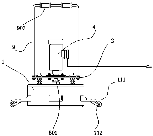
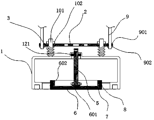
[0033] refer to figure 1 and figure 2The shown building floor polishing device includes a casing 1, and more than two guide rods 101 are annularly arranged on the upper end of the casing 1, and a movable plate 2 is assembled between the two or more guide rods 101. , the upper end of the guide rod 101 passes through the movable plate 2 and is equipped with a limit nut 102, the guide rod 101 is covered with a spring 3, and the spring 3 acts between the housing 1 and the movable plate 2 Between, a motor 4 is flange-connected at the upper end axis of the movable plate 2, and a rotating shaft 5 is interspersed at the axis of the housing 1, and a The connecting sleeve 501 is welded and fixed between the connecting sleeve 501 and the output shaft of the motor 4, and is bolted to the rotating shaft 5. The lower end of the rotating shaft 5 is equipped with a base 6, and the upper end axis of the base 6 is A connecting sleeve 601 is provided, the rotating shaft 5 is inserted into the...

Embodiment 2

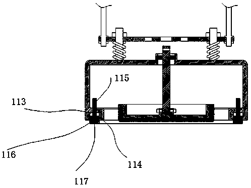
[0035] refer to image 3 As shown, an annular assembly groove 113 is provided at the bottom of the housing 1, and an annular inner ring 114 is installed in the assembly groove 113. The inner ring 114 can move up and down along the assembly groove 113. The upper end of the inner ring 114 A plurality of first guide rods 115 are welded, the first guide rods 115 pass through the assembly groove 113, a collar 116 is arranged at the bottom of the inner ring 114, and a sealing strip 117 is fitted through the collar 116 ; The sealing strip 117 contacts the ground under the action of gravity; when grinding, due to the high-speed rotation of the rotating shaft 5, the particles that are polished will be thrown out, which is dangerous, and the bottom of the shell 1 can not be effective against the ground. There may be gaps for dust leakage. For this reason, we designed the above structure. The inner ring 114 can move up and down. No matter how the shell moves on the ground, the sealing s...

Embodiment 3

[0037] refer to Figure 4 As shown, a vertical rod 991 is welded at the center of the top of the handle rod 9, a lead weight 992 for counterweight is assembled on the vertical rod 991, and a second nut is screwed on the upper end of the vertical rod 991. 993, after the lead block 992 is assembled, the movable plate 2 is pressed down. At this time, the lower end of the polishing cotton 7 touches the ground, and as the number of lead blocks 992 increases, the pressure between the polishing cotton 7 and the ground increases; The function is to increase the self-weight, and use the counterweight of the lead weight to automatically press down the spring without manual depressing. At this time, for each surface of the grinding, the applied downward force is consistent, the overall polishing is better, and no manual depressing is required. The labor force is reduced, and the staff only need to change the grinding position regularly.


PUM


Abstract

The invention discloses a building ground polishing device. The device comprises a shell, two or more guide rods are annularly arranged at the upper end of the shell, a movable plate is assembled between the two or more guide rods, the upper ends of the guide rods penetrate through the movable plate and are provided with limiting nuts, the guide rods are sleeved with springs, the springs act between the shell and the movable plate, and a motor is connected to the axis of the upper end of the movable plate through a flange. Kneeling polishing is not needed, meanwhile, the polishing efficiency is high, and dust can be prevented from being scattered all around.

Description

technical field [0001] The invention relates to a building floor polishing device. Background technique [0002] Ceramic tiles, also known as tiles, are a kind of acid and alkali resistant porcelain or stone formed by refractory metal oxides and semi-metal oxides through the process of grinding, mixing, pressing, glazing and sintering. Or decorative materials, called ceramic tiles. Its raw materials are mostly mixed with clay, quartz sand and so on. [0003] After the floor tiles are pasted, other interior decorations are required, such as suspended ceilings, which will cause damage to the surface of the tiles. Therefore, we will find that the tiles after the decoration are not as bright as the ones on the renderings. [0004] Therefore, it is necessary to simply polish the floor tiles. The existing operation method is to use polishing cotton to polish the floor tiles by the worker kneeling on the ground, holding a grinder; but the dust will rise during the polishing proc...

Claims


Application Information

Patent Timeline
Patent Type & Authority Applications(China)
IPC IPC(8): A47L11/02A47L11/14A47L11/20A47L11/40B24B29/00B24B27/00B24B47/12B24B41/04B24B41/00B24B41/02B24B55/06B24B55/04B24B55/00
CPCA47L11/02A47L11/14A47L11/20A47L11/40A47L11/4038A47L11/4052A47L11/4069A47L11/4072A47L11/4075A47L11/4094B24B27/0007B24B29/00B24B41/007B24B41/02B24B41/04B24B47/12B24B55/00B24B55/04B24B55/06
Inventor 高沛岳增良张春景
Owner 山东诚祥建设集团股份有限公司
Why Eureka
Try Eureka