Movable low-speed driller

A drilling machine, low-speed technology, applied in the direction of boring machine/drilling machine components, boring/drilling, drilling/drilling equipment, etc., can solve the problems of high drilling resistance, poor drilling accuracy, and inability to guarantee drilling accuracy, etc. , to achieve the effect of good moving performance and high drilling precision

Inactive Publication Date: 2013-07-31
王志生
View PDF6 Cites 5 Cited by
  • Summary
  • Abstract
  • Description
  • Claims
  • Application Information

AI Technical Summary

Problems solved by technology

However, they have their own shortcomings in special occasions. For example, bench drills and rocker drills are generally fixed in the workshop. When drilling, the workpiece is clamped on the platform. If a large workpiece is encountered, it cannot be clamped. It is held on its platform, which shows that the bench drill and radial drill have poor mobility
Another example is the magnetic base drill. The drilling is completed by the up and down movement of the driving motor. If the fit is too tight, the resistance during drilling will be too large. If the dovetail groove fits too loosely, the drilling accuracy will not be guaranteed if the drill bit swings left and right. This shows that the drilling accuracy of the magnetic base drill is poor.
Another example is that the speed of ordinary bench drills and magnetic base drills is too high and cannot be adjusted.

Method used


Image

  • Movable low-speed driller
  • Movable low-speed driller

Examples


Embodiment Construction

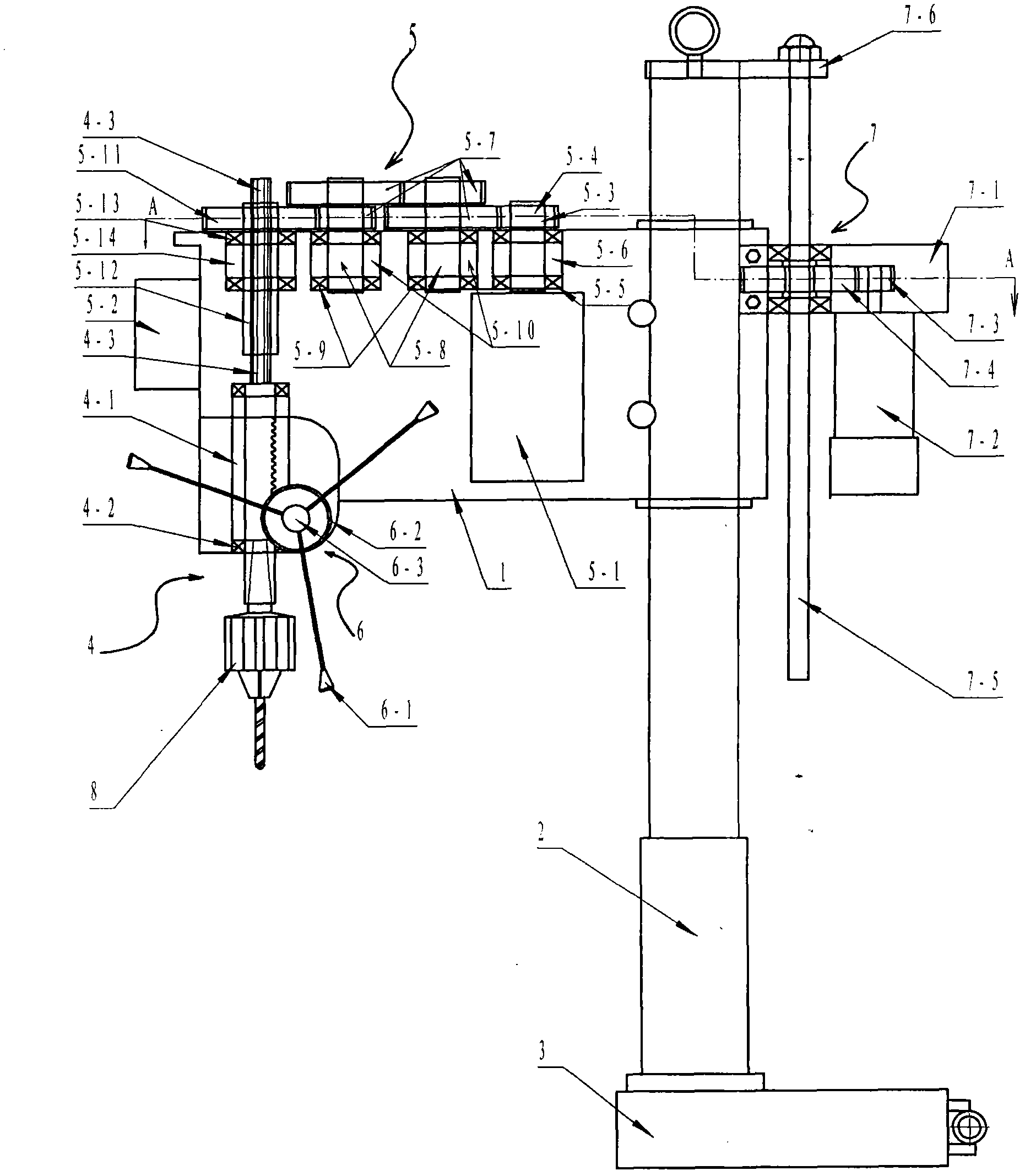
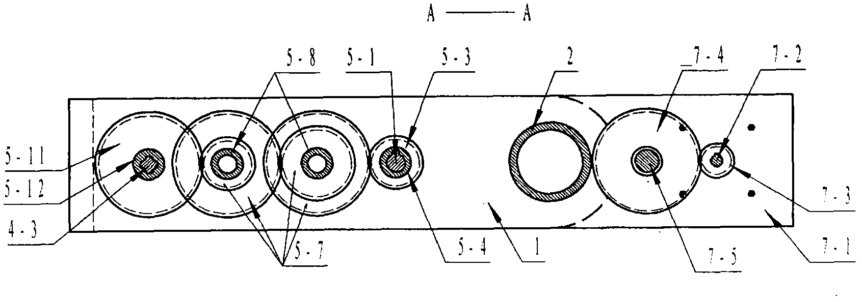
[0045] Below in conjunction with accompanying drawing, the present invention will be further described, as Figure 1-Figure 2 Shown: a movable low-speed drilling machine, including a drill body shell 1, a column 2, a magnetic base 3, a central drill rod device 4, a central drill rod drive deceleration device 5, a central drill rod feeding device 6, and a drill body lifting device 7. Drill chuck 8; the center drill pipe device 4 includes: a center drill pipe guide column barrel 4-1 with a rack on the outer wall, a bearing 4-2, a center drill pipe 4-3, and the center drill The lower end of the rod 4-3 is provided with a Morse taper hole, and the upper end is provided with a spline shaft, and the central drill rod 4-3 is installed on the central drill rod guide cylinder 4- with a rack on the outer wall through the bearings 4-2 at both ends In 1, an overall structure that moves up and down is formed; the central drill pipe feeding device 6 includes: feeding handle 6-1, handle seat...


PUM


Abstract

The invention belongs to the field of machining, and relates to a driller, in particular to a movable low-speed driller. A center drill rod driving reduction device (5) comprises a driving motor (5-1), a driving motor controller (5-2), a driving gear (5-3), a driving gear shaft (5-4), a driving gear bearing (5-5), a driving gear bearing pedestal (5-6), middle gears (5-7), middle gear shafts (5-8), middle gear bearings (5-9), middle gear bearing pedestals (5-10), a driven gear (5-11), a driven gear shaft (5-12), a driven gear bearing (5-13) and a driven gear bearing pedestal (5-14), and is characterized in that the driven gear shaft (5-12) is a hollow shaft; an inner hole of the driven gear shaft (5-12) is provided with a spline; and the spline inner hole is in sliding fit with a spline shaft at the upper end of a center drill rod. The movable low-speed driller has the benefits that the movable low-speed driller is high in drilling accuracy, good in movability and adjustable in rotating speed, and can be absorbed on a large workpiece for use.

Description

Technical field: [0001] The invention relates to a drilling machine, in particular to a movable low-speed drilling machine, which belongs to the field of mechanical processing. technical background: [0002] So far, the bench drills, radial drills and magnetic base drills disclosed on the market have high drilling precision and convenient operation, while the magnetic base drill has the advantages of good moving performance, etc., which are recognized and recognized by the mechanical field. is widely used. However, they have their own shortcomings in special occasions. For example, bench drills and rocker drills are generally fixed in the workshop. When drilling, the workpiece is clamped on the platform. If a large workpiece is encountered, it cannot be clamped. If it is held on its platform, it shows that the bench drill and radial drill have poor mobility. Another example is the magnetic base drill. The drilling is completed by the up and down movement of the driving mot...

Claims


Application Information

Patent Timeline
Patent Type & Authority Applications(China)
IPC IPC(8): B23B39/00B23B47/04B23B47/18
Inventor 王志生
Owner 王志生
Why Eureka
Try Eureka