Electromagnetic type dynamic plate load test detecting device and method

A technology of plate load and detection equipment, which is applied in the direction of applying repeated force/pulsation force to test material strength, foundation structure test, construction, etc., and can solve the dynamic response properties of the foundation that cannot respond well to dynamic loads, and size effects. Errors, loads that are difficult to reach the value, etc., to eliminate the effect of size effect, improve the impact speed and impact energy, easy to carry and use quickly

Active Publication Date: 2013-07-31
北京双杰特科技有限公司
View PDF6 Cites 10 Cited by
  • Summary
  • Abstract
  • Description
  • Claims
  • Application Information

AI Technical Summary

Problems solved by technology

However, in practice, this method has the following problems: one is that the time and cost of the test itself are high due to the application of the load; The measured foundation is only the foundation within the depth range of 2.0 to 2.5 times the diameter (or width) of the bearing plate under the bearing plate; the third is that the measured deformation parameters are only static parameters, which cannot better reflect the foundation under dynamic load ( Dynamic response properties such as high-speed rail, highway foundation, etc.)
However, this method also has the following problems in practical application: first, the ma...

Method used


Image

  • Electromagnetic type dynamic plate load test detecting device and method
  • Electromagnetic type dynamic plate load test detecting device and method
  • Electromagnetic type dynamic plate load test detecting device and method

Examples


Embodiment

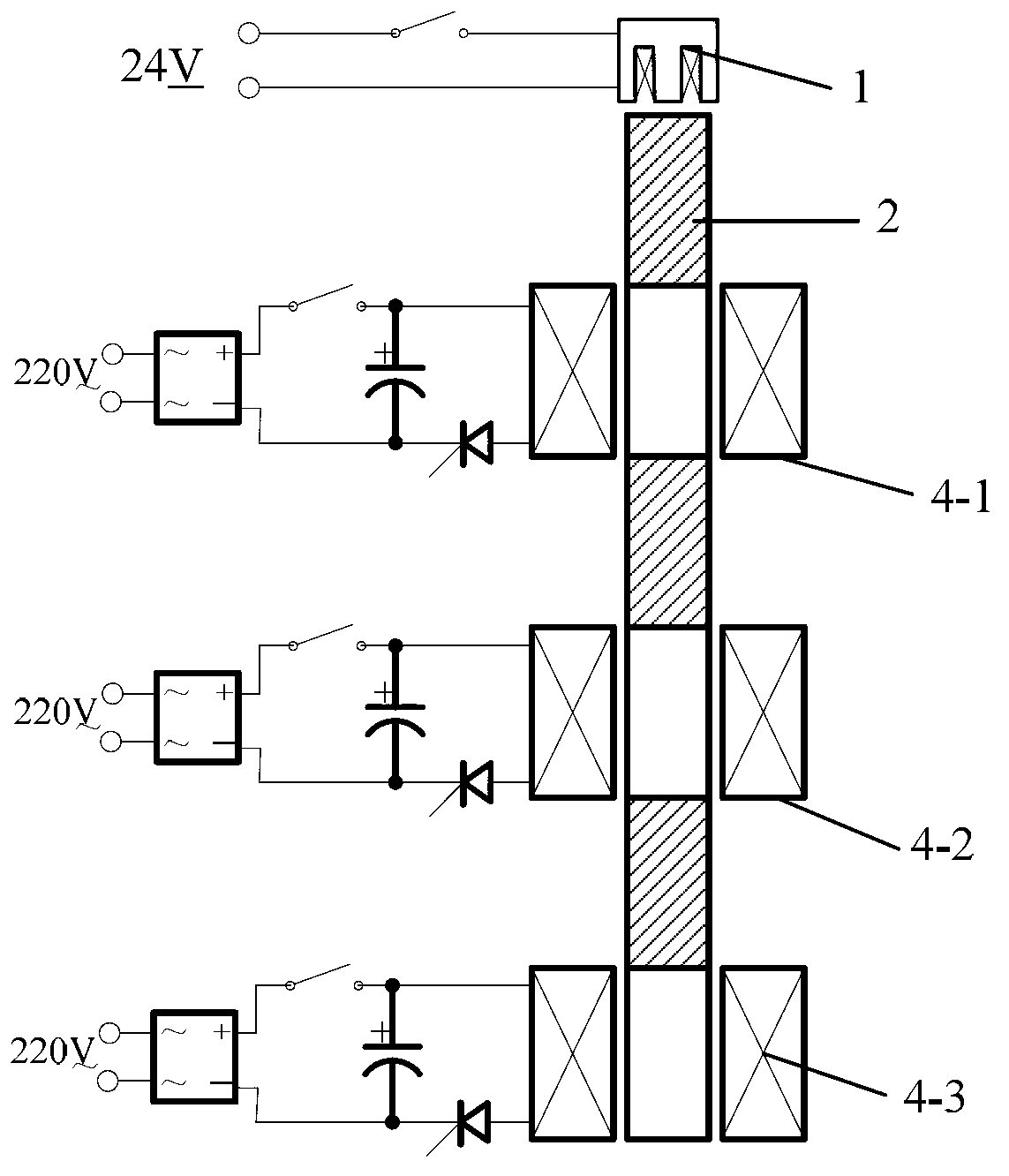
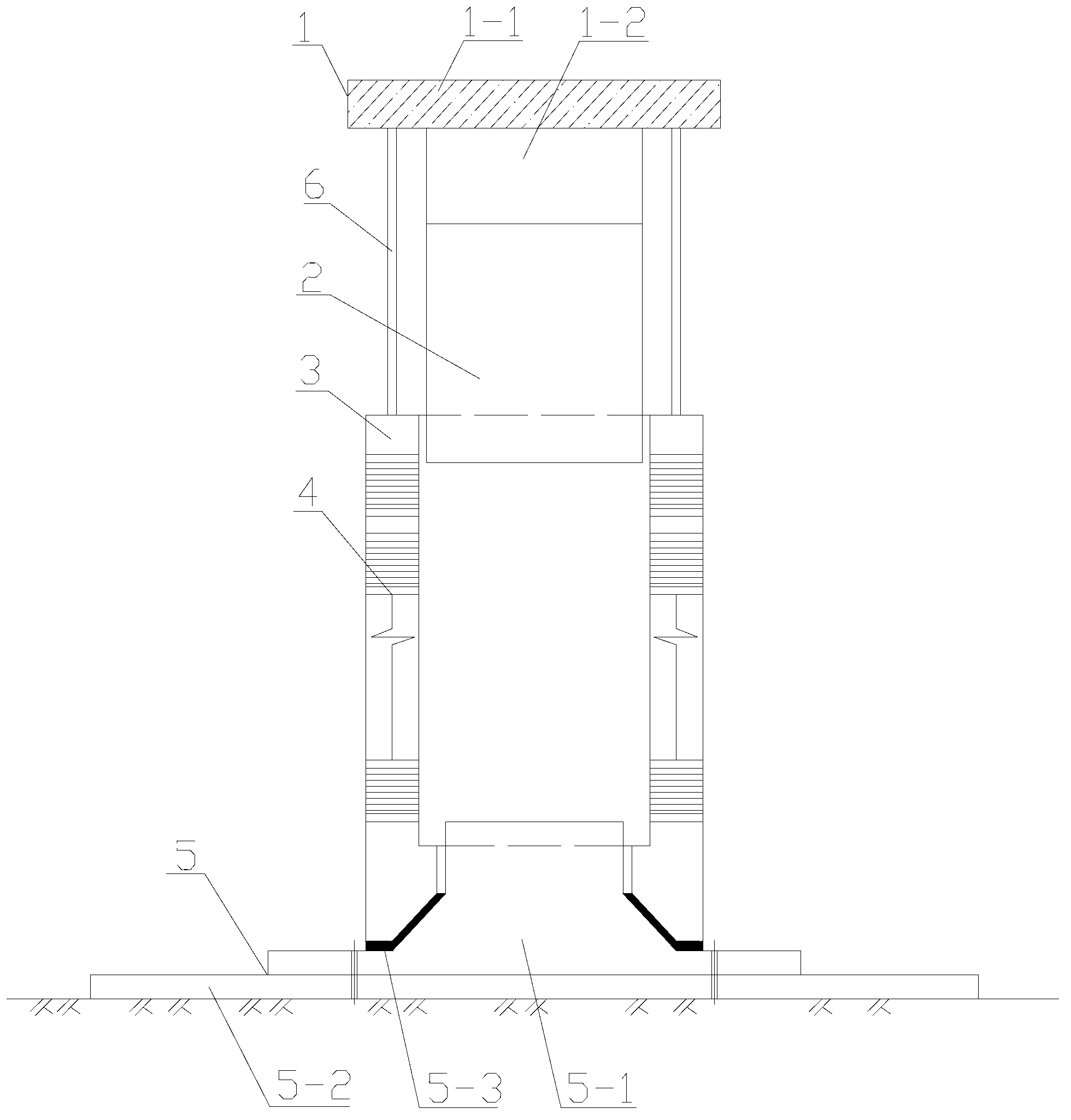
[0035] In this embodiment, a kind of electromagnetic dynamic plate load test detection equipment, such as figure 1 or figure 2 As shown, it includes an electromagnet assembly 1, an impact rod 2, an outer sleeve 3, an electromagnetic acceleration coil 4 and an impact seat plate assembly 5. The electromagnet assembly is arranged above the outer sleeve, the impact rod is arranged in the outer sleeve, and the impact seat The board assembly is arranged under the outer sleeve, and the inner wall of the outer sleeve is provided with multi-stage electromagnetic acceleration coils, and the electromagnetic acceleration coils at each level are respectively connected to the circuit control system; for example figure 2 As shown, the impact seat plate assembly 5 includes an impact seat 5-1 and a pressure-bearing plate 5-2, and the pressure-bearing plate is fixed on the bottom of the impact seat; Inside the outer sleeve.

[0036] In order to reduce the collision or friction between the i...


PUM


Abstract

The invention claims an electromagnetic type dynamic plate load test detecting device and a method. The device disclosed by the invention is characterized in that an electromagnet assembly, an impacting rod and an impact seat plate assembly are respectively arranged above an external sleeve, in the external sleeve and under the external sleeve; a plurality of levels of electromagnet accelerating coils are arranged on the inner side wall of the external sleeve; the levels of electromagnet accelerating coils are respectively in external connection with a circuit control system; the impact seat plate assembly comprises an impact seat and a bearing flat plate; the bearing flat plate is fixed at the bottom of the impact seat; the impact seat plate assembly is statically arranged; the external sleeve is sleeved into the impact seat; and the method disclosed by the invention is characterized by realizing acceleration of the impacting rod by discharging via the plurality of levels of electromagnet accelerating coils in the process of impacting the impact seat via the impacting rod in order to improve the impact energy and speed. By adopting an electromagnetic type graded accelerating impact rod in the device disclosed by the invention, the impact energy and the speed of the impacting rod can be effectively improved; the realized impact force is more than 1000 times to the weight of the impacting rod; and electric supply is taken as a dynamic source, so that the device disclosed by the invention can be better applied to vertical and horizontal foundation plate load test detection.

Description

technical field [0001] The invention relates to the test and detection technology of foundation bearing capacity and deformation modulus in civil engineering, in particular to an electromagnetic dynamic plate load test detection device and method. Background technique [0002] In civil engineering, the foundation deformation modulus and bearing capacity test and detection are the basic means and requirements for the evaluation of foundation engineering properties, and the basic detection stipulated by industry and local regulations. The main index of the test and detection is the characteristic value of the bearing capacity of the foundation. and deformation parameters. [0003] For a long time, the construction industry usually uses the static plate load test method to test the bearing capacity and deformation modulus of the foundation. However, in practice, this method has the following problems: one is that the time and cost of the test itself are high due to the applica...

Claims


Application Information

Patent Timeline
IPC IPC(8): E02D33/00G01N3/38
Inventor 李彰明
Owner 北京双杰特科技有限公司
Why Eureka
Try Eureka