Superconductive magnetic suspension supporting arrangement

A supporting device and magnetic levitation technology, applied in the direction of bearings, shafts and bearings, mechanical equipment, etc., can solve the problems of inconvenient system assembly, complicated assembly and positioning of spherical coils, difficult modular design, etc., and achieve simplified system control and mechanical structure. Effects of Simplifying Troubleshooting Process and Improving Reliability

Active Publication Date: 2013-07-31
INST OF ELECTRICAL ENG CHINESE ACAD OF SCI
View PDF9 Cites 6 Cited by
  • Summary
  • Abstract
  • Description
  • Claims
  • Application Information

AI Technical Summary

Problems solved by technology

Due to the complex structure of the superconducting magnetic levitation support device system, the low-temperature superconducting joint needs to be fabricated on site, which brings inconvenience to the assembly of the system, affects the quality of the superconducting joint, and reduces the reliability of the system
In addition, if there is a technical failure in the support link, it will take a lot of time and effort to check and repair, which also reduces the application effect of the superconducting magnetic levitation support system
The superconducting magnetic levitation device of the Chinese patent ZL01226956.5 uses spherical coils composed of multiple sets of superconducting coils to suspend the superconducting rotor. The assembly and positioning of the spherical coils are complicated, and it is difficult to carry out modular design, and it does not adopt a closed-loop operation mode and cannot be separated. The operation of superconducting power supply affects the application effect

Method used


Image

  • Superconductive magnetic suspension supporting arrangement
  • Superconductive magnetic suspension supporting arrangement
  • Superconductive magnetic suspension supporting arrangement

Examples


Embodiment Construction

[0018] The present invention will be further described below in conjunction with the accompanying drawings and specific embodiments.

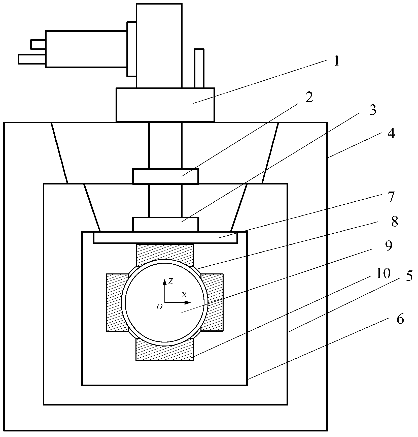
[0019] Such as figure 1 As shown, the mechanical part of the device of the present invention includes a refrigerator 1 , a cryogenic container 4 , a cold shield 5 , a liquid helium container 6 , an installation cover 7 , a rotor cavity 8 , a superconducting rotor 9 and a support module 10 . The refrigerator 1 is installed on the upper end of the cryogenic container 4 , and the primary cold head 2 of the refrigerator 1 is located inside the cryogenic container 4 . The cold screen 5 is in the shape of a roll, placed inside the cryogenic container 4, and fixed on the lower part of the upper end cover of the cryogenic container 4 through a tie rod with high strength and low thermal conductivity. The lower end faces of the head 2 are fastened together by bolts. The liquid helium container 6 is installed inside the cold shield 5, and is fixed on th...


PUM


Abstract

The invention provides a superconductive magnetic suspension supporting arrangement, and six support modules (10) are symmetrically distributed on a reference axis of orthogonal coordinate system whose original point is the center of a rotor chamber (8). A heating power supply (18) is powered on, and a superconductive switch (16) is disconnected, and a superconductive power supply (19) is used for excitation of a superconducting coil (11). A magnetic field generated by the superconducting coil (11) enters from a middle aperture of the superconducting coil (11) to a middle aperture of the superconductive shaping block (12), and then returns from a gap from the superconductive shaping block (12) and the superconducting ring (13) as well as the lower part of the superconducting coil (11) to the middle aperture of the superconducting coil (11) for forming a closed magnetic circuit. The superconductive rotor (9) is suspended by a magnetic repulsion generated by the superconducting coil (11). After excitation of the superconducting coil (11), the heating power supply (18) is closed and the superconductive switch (16) is connected, and then the superconductive power supply (19) is disconnected, and the current of the superconducting coil (11) can provide a stable suspension magnetic field for the superconductive rotor (9).

Description

technical field [0001] The invention relates to a superconducting magnetic suspension supporting device. Background technique [0002] With the development of low temperature technology and the discovery of new superconducting materials, superconducting technology has been more and more widely used. Superconducting instruments developed based on various properties of superconductors play an important role in the economic field, national defense construction and scientific exploration. The superconducting magnetic levitation support system is a frictionless levitation bearing developed based on the low-temperature superconductor Meissner effect, which is widely used in inertial navigation, precision instruments and other fields. The superconducting maglev support system works in a low temperature environment, the chemical activity and expansion coefficient of the material are very low, and the complete diamagnetism and non-resistance characteristics of the superconductor mak...

Claims


Application Information

Patent Timeline
IPC IPC(8): F16C32/04
Inventor 刘建华王秋良胡新宁崔春艳王晖李献
Owner INST OF ELECTRICAL ENG CHINESE ACAD OF SCI
Why Eureka
Try Eureka