
Photoelectricity-navigation-based unmanned road recognition system

A road recognition and unmanned driving technology, applied in character and pattern recognition, two-dimensional position/channel control, instruments, etc., can solve the problems of cumbersome system implementation process, high infrastructure requirements, difficult maintenance, etc., and achieve convenient real-time Observation, low cost, the effect of optimizing the speed

Inactive Publication Date: 2013-07-31
GUANGDONG UNIV OF TECH
View PDF5 Cites 55 Cited by
  • Summary
  • Abstract
  • Description
  • Claims
  • Application Information

AI Technical Summary

Problems solved by technology

At present, the commonly used positioning technologies include magnetic navigation and visual navigation, etc., and the magnetic navigation method often needs to bury certain navigation equipment (such as magnetic nails, wires) on the road. The system implementation process is cumbersome and difficult to maintain, and the route is fixed and the infrastructure requirements are high.

Method used

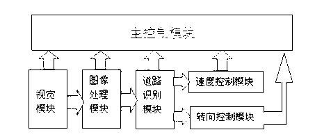
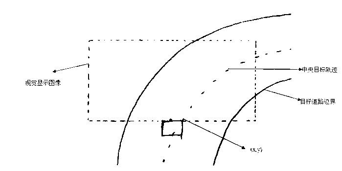
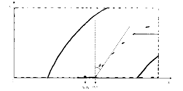

Image

  • Photoelectricity-navigation-based unmanned road recognition system
  • Photoelectricity-navigation-based unmanned road recognition system
  • Photoelectricity-navigation-based unmanned road recognition system

Examples


Embodiment 1

[0038] Below in conjunction with the accompanying drawings, and the specific embodiment when the road boundary is recognized as a green belt by the unmanned vehicle of photoelectric navigation, and the preset color block marker is a turning sign (that is, the speed control module immediately reduces the speed to the set value) value, and get back to the straight road driving state through the corner smoothly) and the present invention will be further described in detail.

[0039] figure 1 It is a schematic diagram of the system structure of the photoelectric navigation-based driverless road recognition system according to the present invention. The system consists of main control module, vision module, image processing module, road recognition module, speed control module and steering control module. The vision module collects images in real time and transmits them to the image processing module. The image processing module extracts the road boundary and transmits it to the r...

Embodiment 2

[0044] How to realize the central target trajectory of rapid tracking simulation under the condition of high speed and large changes in road curvature, on the one hand, depends on the main control module using STM32 processing of μC / OS embedded system and high-performance ARM Cortex-M3 core, on the other hand On the one hand, it depends on the improved multivariate PID algorithm adopted by the steering control module, so that the car can adjust the direction of the steering gear in real time and drive smoothly on the simulated road target trajectory. The algorithm is as follows:

[0045] u = k p e + k i ∫ edt + k d de dt + kθ ;

[0046] Among them, u is the controller output, k p 、k i 、k d and k are proportional coefficient, integr...


PUM


Abstract

The invention discloses a photoelectricity-navigation-based unmanned road recognition system which comprises a vision module, an image processing module, a road recognition module, a speed control module and a steering control module. Turning at a crossroad is mainly achieved through handling a road border, simulating a target trajectory at a track center and recognizing a turning sign. The multi-element PID steering control module and the speed control module realize constantly changing target trajectory when a vehicle rapidly tracks, and realize specified speed and the steering function through identifying color lumps marked by different colors. The intelligent optimized control system is different from a traditional tracking vehicle. The photoelectricity navigation vehicle can realize manless driving without peripheral support through identifying road borders (green belts, fences and the like) in reality and steering signs, thereby having a practical significance.

Description

technical field [0001] The present invention relates to the road recognition system technology of unmanned vehicles, more specifically, relates to an unmanned road recognition system based on photoelectric navigation. Background technique [0002] Unmanned vehicles are the development direction of smart cars in the future. They are especially suitable for tourism, emergency rescue, long-distance high-speed passenger and cargo transportation, and military purposes. lack of. Developed countries have started research on unmanned driving technology since the 1980s, and the development of unmanned vehicles in China is later than that in foreign countries. There are two key technical aspects of unmanned vehicle development: vehicle positioning and vehicle control. These two aspects complement each other and together form the basis of self-driving cars. At present, the commonly used positioning technologies include magnetic navigation and visual navigation, etc., but the magneti...

Claims


Application Information

Patent Timeline
Patent Type & Authority Applications(China)
IPC IPC(8): G05D1/02G06K9/00
Inventor 柯宗泽苏成悦李欣怡刘柏芳邹志明
Owner GUANGDONG UNIV OF TECH
Learn More