Method for designing receiving transducer of electromagnetic ultrasonic surface wave

A technology of electromagnetic ultrasonic and design method, applied in the direction of instrumentation, calculation, electrical digital data processing, etc., can solve the problems of complex processing, strong receiving noise, etc., and achieve the effect of simple operation and easy analysis

Inactive Publication Date: 2013-07-31
HARBIN INST OF TECH
View PDF2 Cites 6 Cited by
  • Summary
  • Abstract
  • Description
  • Claims
  • Application Information

AI Technical Summary

Problems solved by technology

[0003] In order to solve the problems of strong receiving noise and complex processing in the design of the existing electromagnetic ultrasonic surface wave receiving transducer, the present invention proposes a design method for the electromagnetic ultrasonic surface wave receiving transducer

Method used


Image

  • Method for designing receiving transducer of electromagnetic ultrasonic surface wave
  • Method for designing receiving transducer of electromagnetic ultrasonic surface wave
  • Method for designing receiving transducer of electromagnetic ultrasonic surface wave

Examples


specific Embodiment approach 1

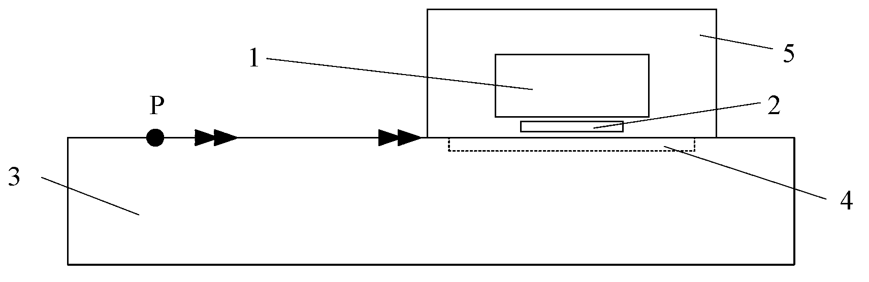
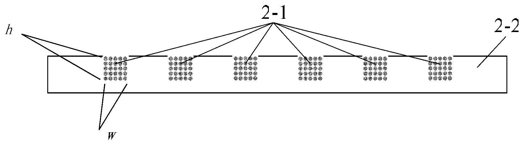
[0020] Specific implementation mode one: combine figure 1 and figure 2 Describe this embodiment, the electromagnetic ultrasonic surface wave receiving transducer design method described in this embodiment, to realize the design method needs to model and solve the receiving process of the electromagnetic ultrasonic surface wave transducer, and carry out the electromagnetic ultrasonic surface wave receiving process Complete and accurate description, analyze the influence of different electromagnetic ultrasonic transducer parameters on the received signal strength, so as to obtain the optimal transducer parameter combination; the model mainly includes permanent magnet 1, electromagnetic ultrasonic surface wave transducer receiving coil 2 , the metal test piece 3 to be tested, the refinement layer 4 and the air far field 5; the receiving coil 2 of the electromagnetic ultrasonic surface wave transducer is a meander coil structure, which is formed by winding an enameled wire 2-1 on...

specific Embodiment approach 2

[0032] Specific implementation mode two: combination figure 1 and figure 2 This embodiment is described. In this embodiment, the thickness of the metal test piece 3 to be tested is greater than 4 times the wavelength of the ultrasonic surface wave and less than 10 times the wavelength of the ultrasonic surface wave. Other steps are the same as in the first embodiment.

specific Embodiment approach 3

[0033] Specific implementation mode three: combination figure 1 and figure 2 This embodiment is described. In this embodiment, in step 2, the certain lift-off distance is 0.1 mm to 2 mm. Other steps are the same as in the first embodiment.


PUM


Abstract

The invention relates to a method for designing a receiving transducer of an electromagnetic ultrasonic surface wave, and aims to solve the problems that the conventional design of the receiving transducer of the electromagnetic ultrasonic surface wave is strong in noise receiving and complicated in processing. The method comprises the steps as follows: establishing the geometrical model of each element; setting material attributes; partitioning physical field solving areas; setting structural field parameters; setting electromagnetic field parameters; performing finite element subnetting and finite element solution; calculating induced voltage signals in receiver coils with different parameters; and completing the design of the receiving transducer of the electromagnetic ultrasonic surface wave eventually. According to the method for receiving the receiving transducer of the electromagnetic ultrasonic surface wave provided by the utility model, the modeling and solving for a receiving process of the transducer of the electromagnetic ultrasonic surface wave are achieved by the design method, the complete and accurate description of the receiving process of the electromagnetic ultrasonic surface wave is realized, and the influence on the received signal strength by parameters of different electromagnetic ultrasonic transducer is analyzed, so that the optimal transducer parameter combination is obtained.

Description

technical field [0001] The invention relates to a design method of an electromagnetic ultrasonic surface wave receiving transducer. Background technique [0002] The electromagnetic ultrasonic surface wave receiving transducer generally adopts a meandering coil structure, mainly in the form of a printed circuit board and a skeleton. Among them, the skeleton form transducer is made of enameled wire winding, which is more efficient than the printed circuit board form transducer in receiving electromagnetic ultrasonic surface wave signals, and has been widely used in the field of electromagnetic ultrasonic applications. However, at present, the design of the electromagnetic ultrasonic surface wave receiving transducer in the form of skeleton is mainly based on experience. If you want to use enameled wires with a diameter of 0.19mm and a skeleton groove with a size of 1mm×1mm to design an electromagnetic ultrasonic surface wave receiving transducer, generally place 5 enameled w...

Claims


Application Information

Patent Timeline
Patent Type & Authority Applications(China)
IPC IPC(8): G06F17/50
Inventor 王淑娟李智超高孝天苏日亮刘博许霁李永虔康磊翟国富
Owner HARBIN INST OF TECH
Why Eureka
Try Eureka