LED fluorescent powder coating technology

A technology of fluorescent powder and nano-phosphor powder, which is applied in the direction of electrical components, circuits, semiconductor devices, etc., to achieve the effects of avoiding glare, increasing life, and improving work stability

Active Publication Date: 2013-07-31
深圳市三创客科技有限公司
View PDF4 Cites 0 Cited by
  • Summary
  • Abstract
  • Description
  • Claims
  • Application Information

AI Technical Summary

Problems solved by technology

[0004] Aiming at the shortcomings of the existing LED phosphor packaging, the present invention, as an important part of the whole LED phosphor coating technical solution proposed by the inventor, provides a LED phosphor coating technology, which is applied to LED lighting and overcomes the Disadvantages of existing LED phosphor packaging

Method used


Image

  • LED fluorescent powder coating technology
  • LED fluorescent powder coating technology
  • LED fluorescent powder coating technology

Examples


Embodiment Construction

[0025] In order to make the object, technical solution and advantages of the present invention clearer, the present invention will be further described in detail below in conjunction with the accompanying drawings and embodiments. It should be understood that the specific embodiments described here are only used to explain the present invention, not to limit the present invention.

[0026] The present invention will be further described in detail below in conjunction with the above-mentioned drawings and embodiments.

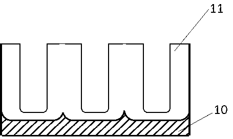
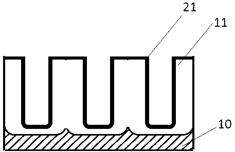
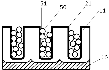
[0027] Examples of the present invention Figure 1 to Figure 5 Shown: the present invention is realized in this way, a kind of LED fluorescent powder coating technology, the aluminum alloy surface is used as the reflective surface of LED light source, aluminum alloy is through surface treatment, and surface treatment includes aluminum alloy anodic oxidation treatment, nano phosphor powder surface modification Processing, nano phosphor filling processing and hol...


PUM

PropertyMeasurementUnit
diameteraaaaaaaaaa
depthaaaaaaaaaa
depthaaaaaaaaaa

Abstract

The invention discloses an LED fluorescent powder coating technology. An aluminum alloy surface is taken as a diffuse reflection surface of an LED light source; aluminum alloy is subjected to surface treatment; the surface treatment comprises aluminum alloy anodic oxidation treatment, nano fluorescent powder surface finish treatment, nano fluorescent powder filling treatment and hole sealing treatment; the aluminum alloy surface is taken as the diffuse reflection surface and partially converts blue light emitted by an LED into yellow light through the conversion function of nano fluorescent powder, and the yellow light and the blue light are mixed to form white light. The LED fluorescent powder coating technology has the technical benefits as follows: the fluorescent powder doesn't block radiating of the LED, simultaneously, work of the fluorescent powder at higher temperature can be avoided, and the LED coating technology is a preferable technical scheme of a superhigh power LED light source.

Description

technical field [0001] The invention belongs to the technical field of LED lighting, and in particular relates to an LED fluorescent powder coating technology. Background technique [0002] At present, LED phosphor powder is usually mixed with glue first, and then glue is applied to the surface of the LED. Taking blue LED as an example, after the blue light is emitted from the LED, part of the blue light and the fluorescent powder are converted into yellow light, yellow light and The blue light mixes so that what is emitted becomes white light. Since the glue is often a poor conductor of heat, the blue light is partially converted into heat energy after being absorbed by the phosphor, which will cause problems such as glue aging, reduced luminous efficiency of the phosphor after being heated, and color temperature drift. At the same time, the temperature of the LED will also rise. , shorten the service life of LED. In addition, the light emitted directly from the LED is ve...

Claims


Application Information

Patent Timeline
Patent Type & Authority Applications(China)
IPC IPC(8): H01L33/50H01L33/60H01L33/64
Inventor 陈玥娟任立元
Owner 深圳市三创客科技有限公司
Why Eureka
Try Eureka