
Method for quenching mold

A mold and oil cooling technology, applied in the direction of quenching agent, manufacturing tools, furnace types, etc., can solve the problems of poor productivity, long time, difficult to control cooling speed, etc., and achieve the effect of increasing life and improving surface toughness

Active Publication Date: 2013-07-31
HITACHI METALS LTD +1
View PDF7 Cites 2 Cited by
  • Summary
  • Abstract
  • Description
  • Claims
  • Application Information

AI Technical Summary

Problems solved by technology

[0013] The inventors of the present invention have studied the martensitic quenching method, and found that under the conditions disclosed in the above-mentioned Patent Document 1 and Patent Document 2, the toughness of the surface of the mold is insufficient, and there is room for further improvement.
[0014] Furthermore, if the technology disclosed in Patent Document 3 and Patent Document 4 is applied to a mold whose volume is generally larger than that of a gear, etc., it will be difficult to control the cooling rate, and the surface of the mold will drop to a temperature below the Ms point during rapid cooling.
At this time, the temperature inside the mold hardly drops, and if it is taken out from the quenching oil, the temperature of the surface becomes higher than the Ms point again due to the retained heat inside the mold, so that the metal structure becomes unstable, and hardness fluctuations occur on the mold. difference
Furthermore, in the case of a heavy mold, if it is attempted to maintain a constant temperature until it reaches a temperature near the Ms point, the time required will become too long, and productivity will also significantly deteriorate.

Method used


Image

  • Method for quenching mold
  • Method for quenching mold
  • Method for quenching mold

Examples


example 1

[0078] The present invention is described in more detail using the following examples.

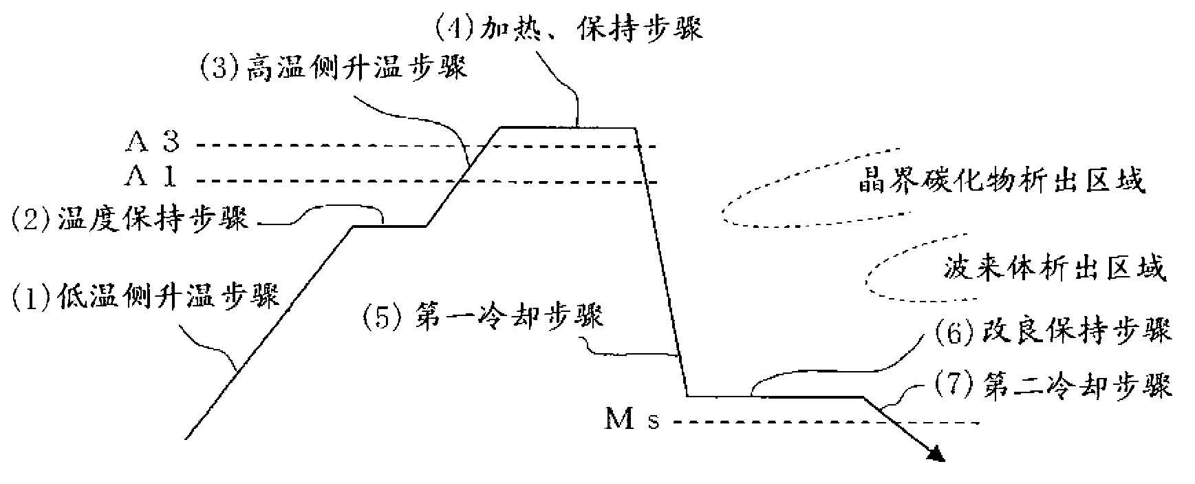
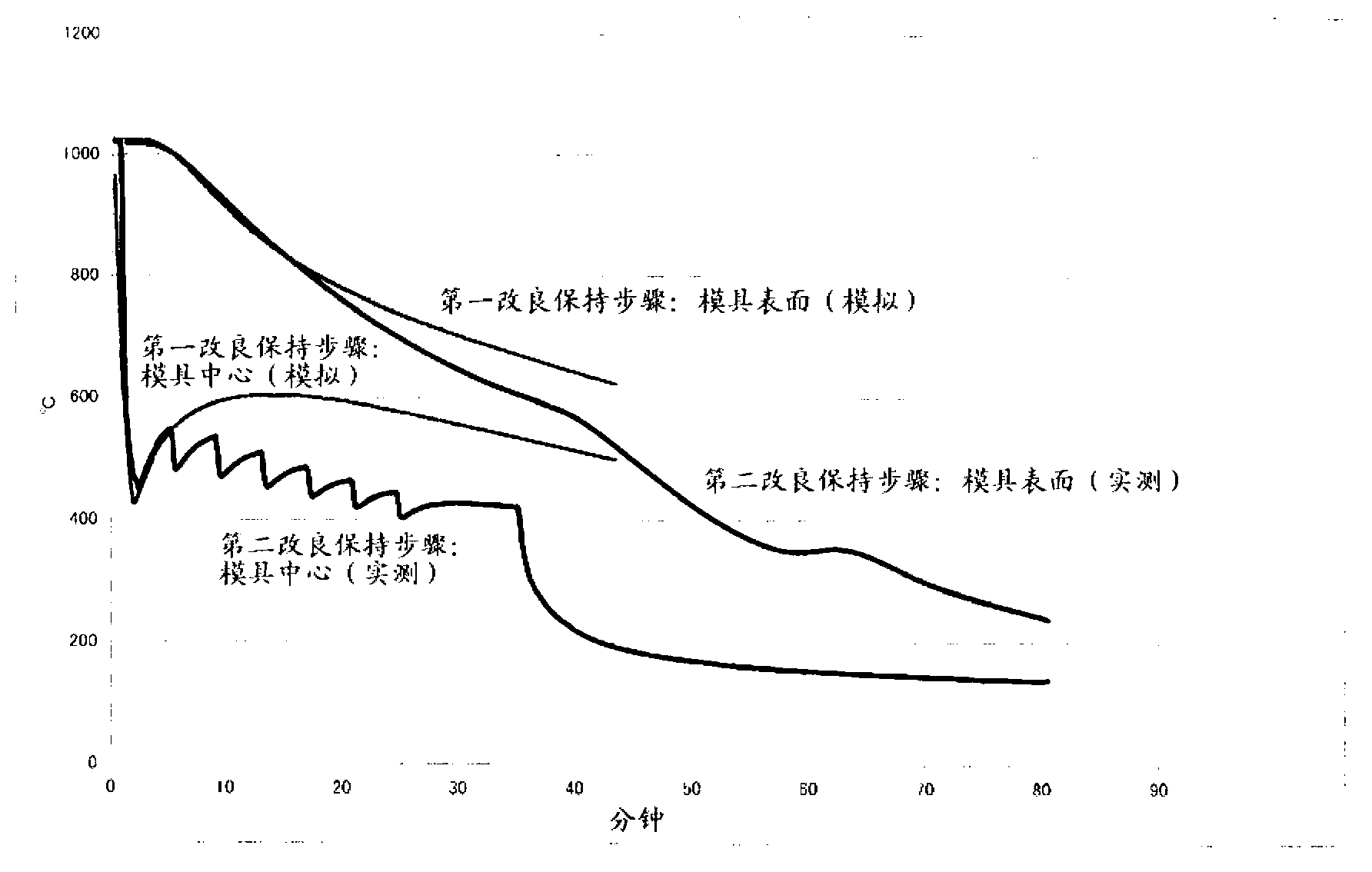
[0079] Cut out a block of 300 mm (w) x 300 mm (l) x 300 mm (t) from the mold material for a hot mold with the composition shown in Table 1, and make the first sample for the first improvement holding step and the second improvement Holds the second profile of the step. The prepared alloys are all materials equivalent to Japan Industrial Standard (JIS)-SKD61.

[0080] The A1 transformation point of the alloy is 850°C, the A3 transformation point is 895°C, the Ms point is 300°C, and the nose (nose) of the grain boundary carbide precipitation region is 700°C-20 minutes.

[0081] [Table 1]

[0082] (wt% (weight percentage))

[0083] C

Si

mn

Cr

Mo

V

The remaining part

0.37

0.95

0.40

5.10

1.36

0.95

Fe and impurities

[0084] Quenching treatment was performed using the above-mentioned samples. ...


PUM


Abstract

A method for quenching a mold, comprising: a heating / retention step of heating the mold and retaining the mold at a temperature which is equal to or higher than an A3 transformation point and lower than 1150 DEG C; a first cooling step of, subsequent to the heating / retention step, immersing the mold in an oil vessel to cool the mold by oil cooling until the surface of the mold has a temperature which is equal to or lower than 700 DEG C and higher than an Ms point; an improved retention step of, subsequent to the first cooling step, pulling the mold out of the oil vessel to interrupt the oil cooling and retaining the mold until the surface of the mold has a temperature range which is higher than the Ms point and lower than the temperature at which the difference between the temperature of the surface of the mold and the temperature of the inside of the mold falls within 200 DEG C; and a second cooling step of, subsequent to the improved retention step, cooling the mold at a cooling rate of 1-50 DEG C / min until the surface of the mold has a temperature of 200 DEG C.

Description

technical field [0001] The invention relates to a quenching method of a mold. Background technique [0002] High hardness and high toughness are required for the mold, and the characteristics of the mold are greatly affected by the quenching method. [0003] When the temperature is raised, in order to maximize the solid solution of the alloying elements, a high quenching temperature is selected within the range where the grains are not coarsened. In addition, in order to obtain high toughness during quenching, it is necessary to refine the crystal grains while suppressing the precipitation of carbides to the grain boundaries, and it is also necessary to prevent bainitic transformation. At this time, rapid cooling is required, but on the other hand, if rapid cooling is performed, the strain and deformation of the mold will increase, so it is necessary to appropriately control the cooling rate. Therefore, various methods have been proposed in the past, but the method of adju...

Claims


Application Information

Patent Timeline
Patent Type & Authority Applications(China)
IPC IPC(8): C21D9/00C21D1/18C21D1/19
CPCC21D1/56C21D1/58C21D9/0068C21D1/19B22D30/00C21D1/18
Inventor 片冈仁川上贵司
Owner HITACHI METALS LTD
Learn More