Method and circuit arrangement for charging an intermediate circuit capacitor

A technology of intermediate circuits and circuit devices, which is applied to emergency protection circuit devices, battery circuit devices, and electrical devices for limiting overcurrent/overvoltage, which can solve problems such as high power loss and high voltage, and achieve reliable construction , the effect of shortening the duration

Active Publication Date: 2013-07-31
ROBERT BOSCH GMBH +1
View PDF4 Cites 1 Cited by
  • Summary
  • Abstract
  • Description
  • Claims
  • Application Information

AI Technical Summary

Problems solved by technology

[0015] However, the disadvantage here is that at the beginning of the flow through the current source, that is to say while the intermediate circuit capacitor is still discharging, a high voltage is applied, which leads to high power losses

Method used


Image

  • Method and circuit arrangement for charging an intermediate circuit capacitor
  • Method and circuit arrangement for charging an intermediate circuit capacitor
  • Method and circuit arrangement for charging an intermediate circuit capacitor

Examples


Embodiment Construction

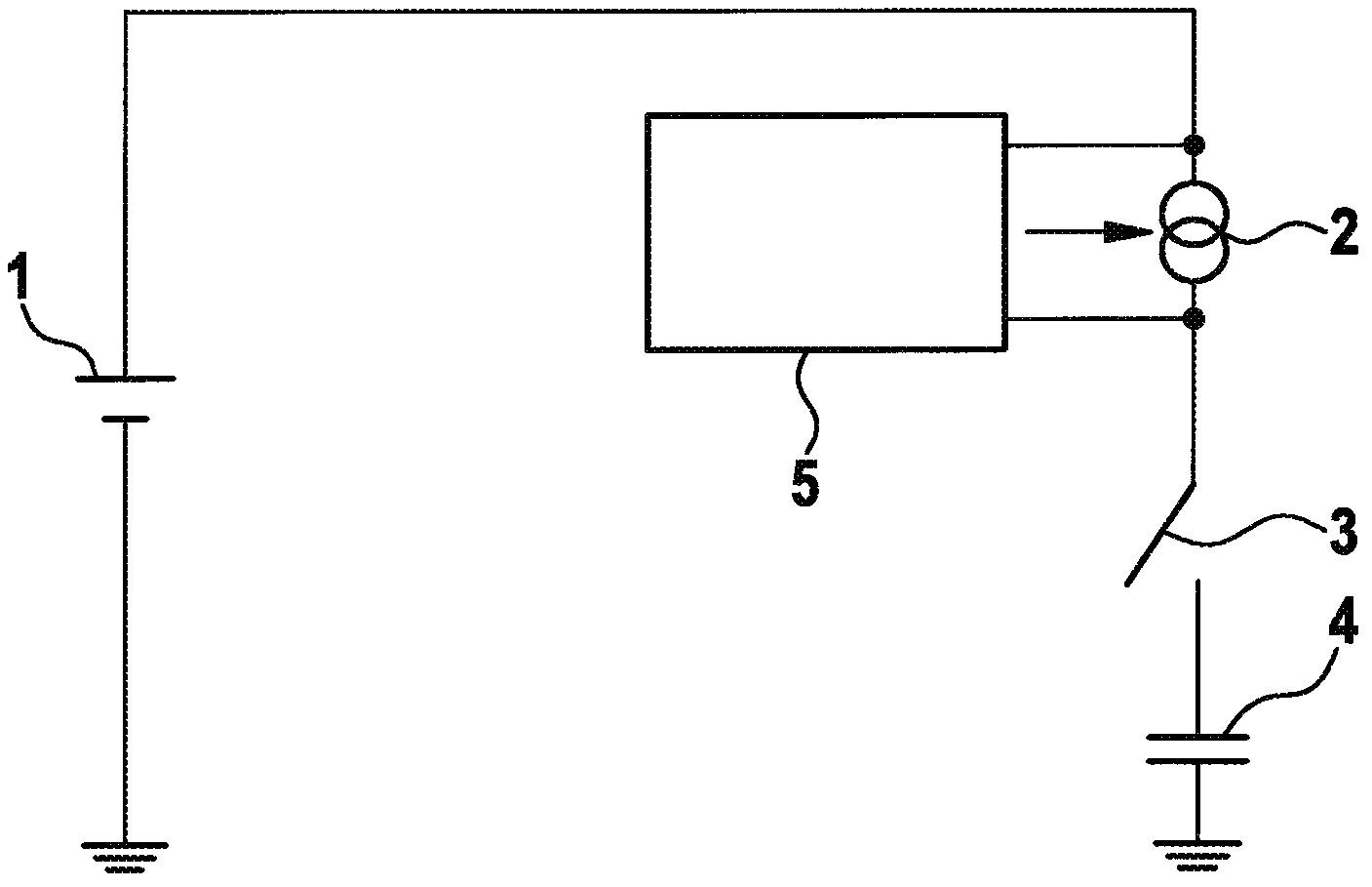
[0034] exist figure 1 The basic principle of the solution according to the invention is shown in . A battery 1 , in the present exemplary embodiment a lithium-ion battery, is connected to a current source 2 . According to the invention, the voltage at the current source 2 is detected and the current is adjusted such that a constant power loss occurs in the current source 2 during the entire charging process.

[0035] Current source 2 is connected via switch 3 to intermediate circuit capacitor 4 . A regulating circuit 5 is arranged in parallel with the current source 2 , by means of which the current for charging the intermediate circuit capacitor 4 can be regulated such that a constant power loss occurs in the current source 2 during the entire charging process.

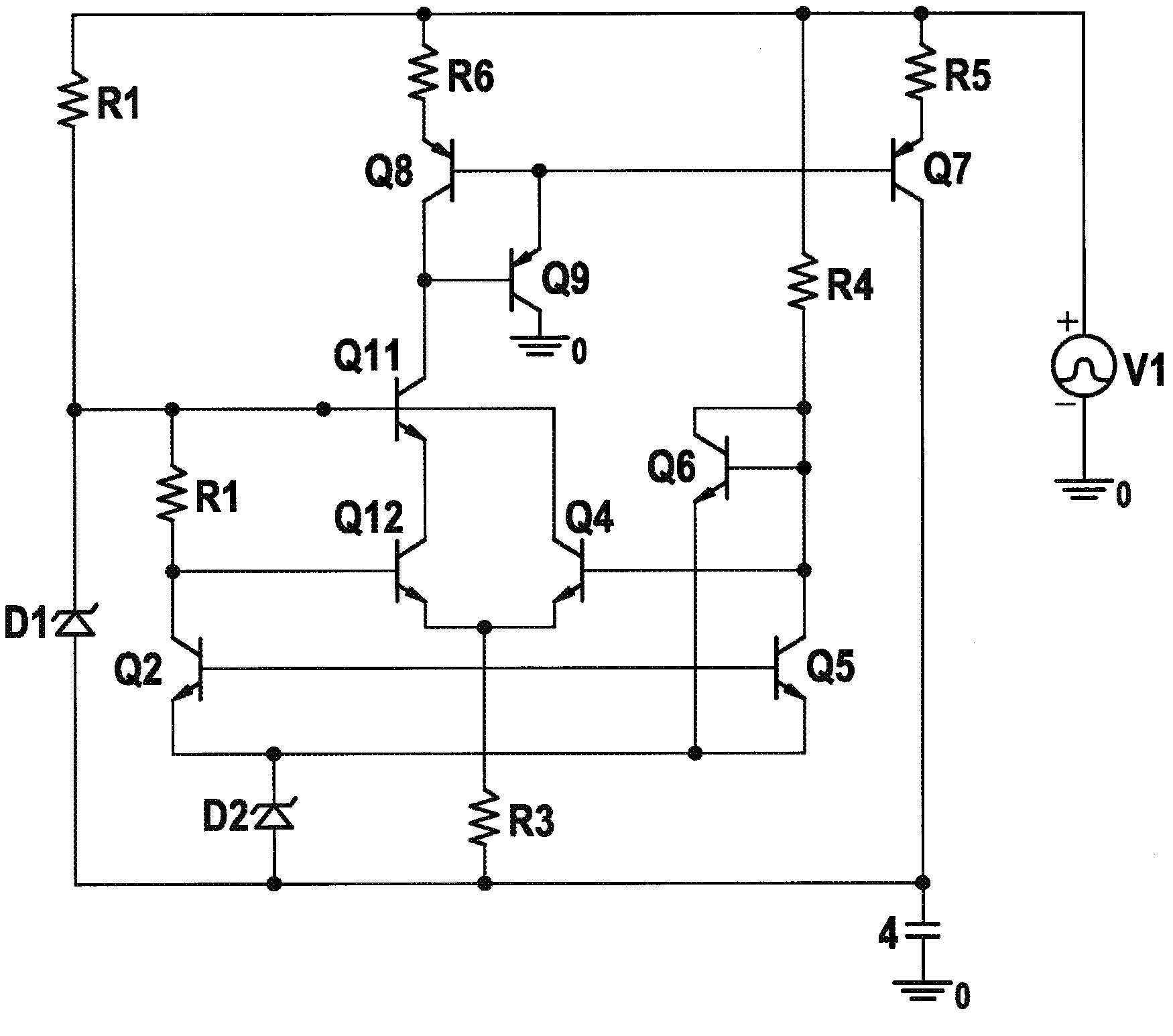
[0036] figure 2 One possible embodiment of the invention is shown. Here, transistors Q2, Q12, Q4, Q5, and Q6 operate as a divider circuit. This constant power loss is set via Zener diode 4 and resistor R2 as a...


PUM


Abstract

A method for charging an intermediate circuit capacitor in a precharging unit includes charging the intermediate circuit capacitor via a current source and adjusting the supplied current in such a manner that a constant power loss is produced in the current source during the entire charging operation. A circuit arrangement includes a battery which is connected to a current source which is connected to an intermediate circuit capacitor via a switch. An adjusting circuit is arranged in parallel with the current source and can be used to adjust the current for charging the intermediate circuit capacitor. The current is adjusted in such a manner that a constant power loss is produced in the current source during the entire charging operation.

Description

technical field [0001] The invention relates to a method for charging an intermediate circuit capacitor and a circuit arrangement for implementing the method. Background technique [0002] Whether for stationary applications (such as wind power generation equipment) or for mobile applications (such as applications in motor vehicle technology), the future development of battery systems will be directed towards new battery systems. Very high demands were made. [0003] The background to this requirement is that a failure of the battery can lead to failure of the entire system. In electric vehicles, for example, a failure of the traction battery can lead to so-called "squatting". [0004] In wind power installations, failure of the storage battery can even lead to safety-related problems, since the storage battery is used here, for example, to protect the installation from impermissible operating states in the event of high winds via the distribution of the rotor blades. [...

Claims


Application Information

Patent Timeline
Patent Type & Authority Applications(China)
IPC IPC(8): H02J7/34H02H9/00
CPCH02J7/34B60L2270/20B60L3/003H02J7/345
Inventor S·布茨曼
Owner ROBERT BOSCH GMBH
Why Eureka
Try Eureka