Hydraulic supporting control mechanism of roller connecting shaft and relevant puncher and relevant pipe milling machine

A technology of hydraulic support and control mechanism, applied in rolling mill control devices, metal rolling, metal rolling, etc., can solve the problems of the sinking of the roll joint shaft, the large rotation diameter of the roll joint shaft, and the reduction of the force on the roll joint 107, etc. Achieve the effect of prolonging the life, reducing the diameter of rotation and improving the force

Active Publication Date: 2013-08-07
TAIYUAN HEAVY IND
View PDF5 Cites 0 Cited by
  • Summary
  • Abstract
  • Description
  • Claims
  • Application Information

AI Technical Summary

Problems solved by technology

[0003] When the current piercing machine or rolling mill is rolling, the roll joint shaft is not supported. Due to the heavy roll joint shaft, the self-weight causes the roll joint shaft to sink, resulting in a large rotation diameter when the roll joint shaft rotates, which affects the reducer joint 107 and the roll joint. 107 stress and reduce its service life

Method used


Image

  • Hydraulic supporting control mechanism of roller connecting shaft and relevant puncher and relevant pipe milling machine
  • Hydraulic supporting control mechanism of roller connecting shaft and relevant puncher and relevant pipe milling machine
  • Hydraulic supporting control mechanism of roller connecting shaft and relevant puncher and relevant pipe milling machine

Examples


Embodiment Construction

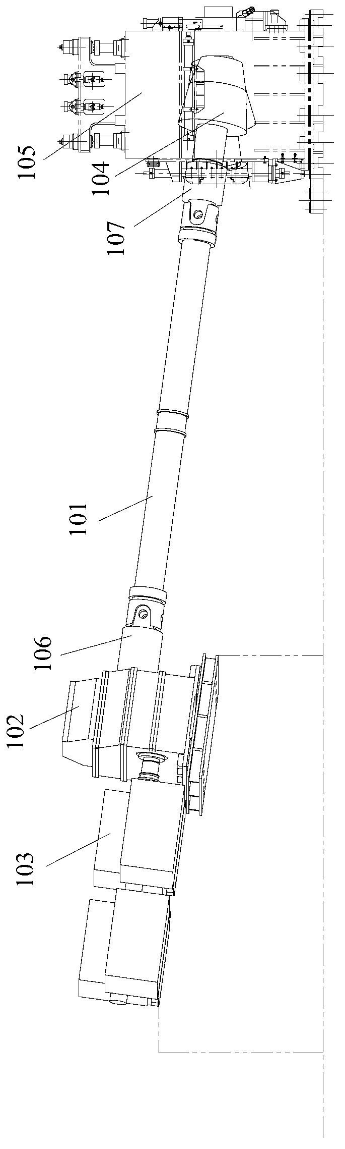
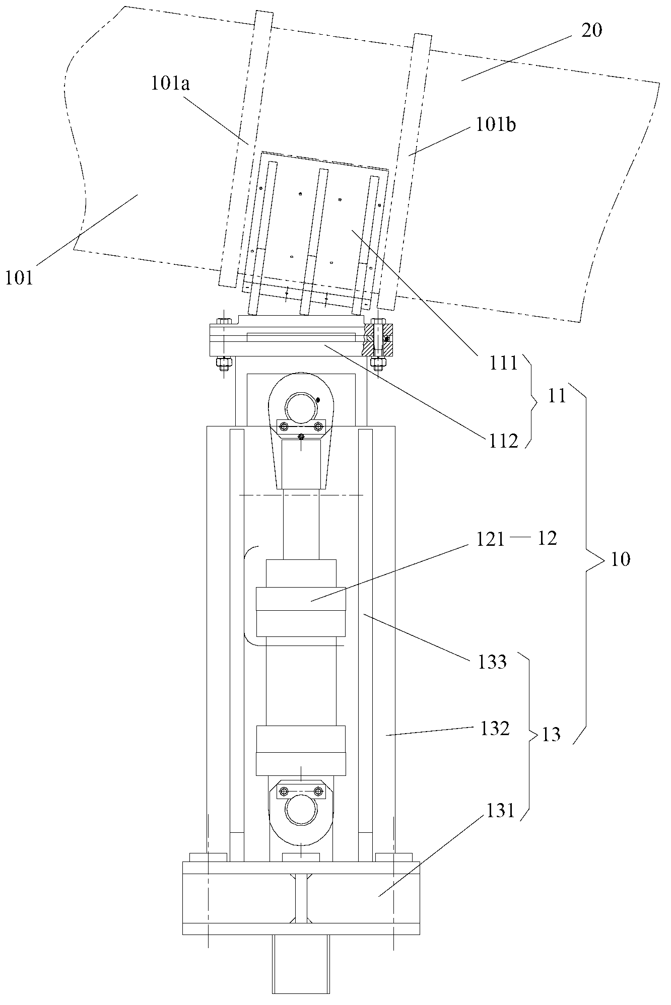
[0018] figure 2 Shown is a schematic diagram of the hydraulic support control mechanism of the roll joint shaft according to an embodiment of the present invention. Such as figure 2 As shown, the present invention is provided with a hydraulic control support mechanism 10 for supporting the roll connection shaft 20 below the roll connection shaft 20. The hydraulic control support mechanism 10 includes a connection shaft support seat 11 that contacts and supports the roll connection shaft 20, a hydraulic support Control system 12 and hydraulic cylinder mount 13.

[0019] The shaft connection support seat 11 supports the roll connection shaft 20 upwards from the lower middle part of the roll connection shaft 20 , and the shaft connection support seat 11 and the roll connection shaft 20 are in sliding contact with the bearing bush. The hydraulic cylinder 121 of the hydraulic support control system 12 is arranged in the hydraulic cylinder installation seat 13, and the hydraulic...


PUM


Abstract

The invention provides a hydraulic supporting control mechanism of a roller connecting shaft and a relevant puncher and a relevant pipe milling machine. The hydraulic supporting control mechanism of the roller connecting shaft is used for supporting the roller connecting shaft dynamically and comprises a connecting shaft supporting base, a hydraulic supporting control system and a hydraulic cylinder installing base. The connecting shaft supporting base contacts with and supports the roller connecting shaft, the hydraulic cylinder installing base is installed on a foundation, a hydraulic cylinder of the hydraulic supporting control system is installed in the hydraulic cylinder installing base, and the hydraulic cylinder can drive the connecting shaft supporting base to move up and down or support the roller connecting shaft in a floating mode. Due to the fact that constant supporting force exists, a sinking range of the roller connecting shaft is limited, rotary diameter of the roller connecting shaft is reduced, simultaneously the stress of handles at two ends of the roller connecting shaft is improved, and the service life of the handles is prolonged.

Description

technical field [0001] The invention relates to a rolling mill, in particular to a hydraulically controlled support system for the roll joint shaft of a piercing machine or a pipe rolling mill and related piercing machines and pipe rolling mills. Background technique [0002] During the steel rolling process, the main function of the roll shaft is to transmit the speed and torque of the reducer to the roll, so that the roll rotates and bites into the pipe to achieve the purpose of rolling. figure 1 Shown is a structural schematic diagram of an existing power transmission system including a roll joint. Such as figure 1 As shown, the two ends of the roll connecting shaft 101 are respectively connected with the reducer handle 106 and the roll handle 107, the reducer handle 106 is connected with the reducer 102, the reducer 102 is connected with the motor 103; the roll handle 107 is connected with the roll 104, and the roll 104 Installed in the frame 105. During rolling, the ...

Claims


Application Information

Patent Timeline
Patent Type & Authority Applications(China)
IPC IPC(8): B21B25/00B21B37/78
Inventor 曹美忠
Owner TAIYUAN HEAVY IND
Why Eureka
Try Eureka