Jawless Tube Chuck

A claw clamp and pipe clamp technology, which is applied in the field of clawless pipe clamps, can solve the problems of complex structure and low work efficiency of the chuck, and achieve the effect of simplified transmission transition, simplified structure and light weight.

Active Publication Date: 2017-07-11
常州市力源恒机械有限公司
View PDF8 Cites 0 Cited by
  • Summary
  • Abstract
  • Description
  • Claims
  • Application Information

AI Technical Summary

Problems solved by technology

[0004] The technical problem to be solved by the present invention is: in order to solve the technical problems of complex structure and low work efficiency of the chuck with claws in the prior art, the present invention provides a clawless pipe chuck

Method used


Image

  • Jawless Tube Chuck
  • Jawless Tube Chuck
  • Jawless Tube Chuck

Examples


Embodiment Construction

[0037] The present invention is described in further detail now in conjunction with accompanying drawing. These drawings are all simplified schematic diagrams, which only illustrate the basic structure of the present invention in a schematic manner, so they only show the configurations related to the present invention.

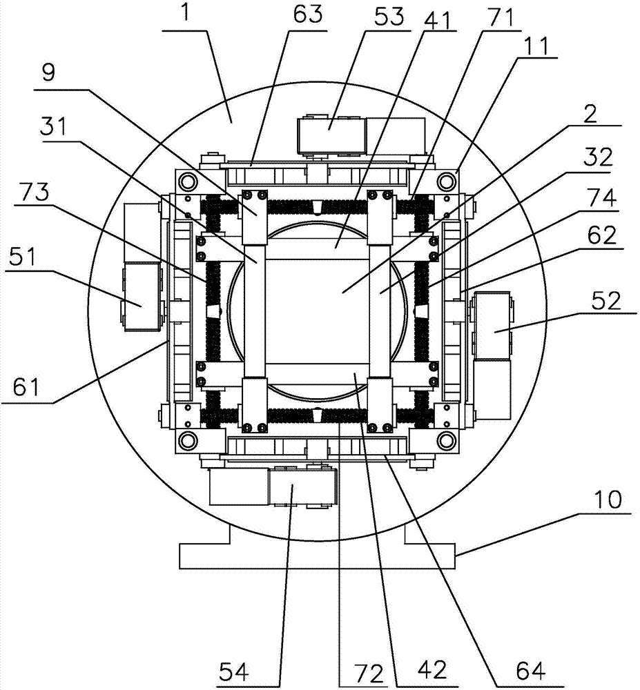
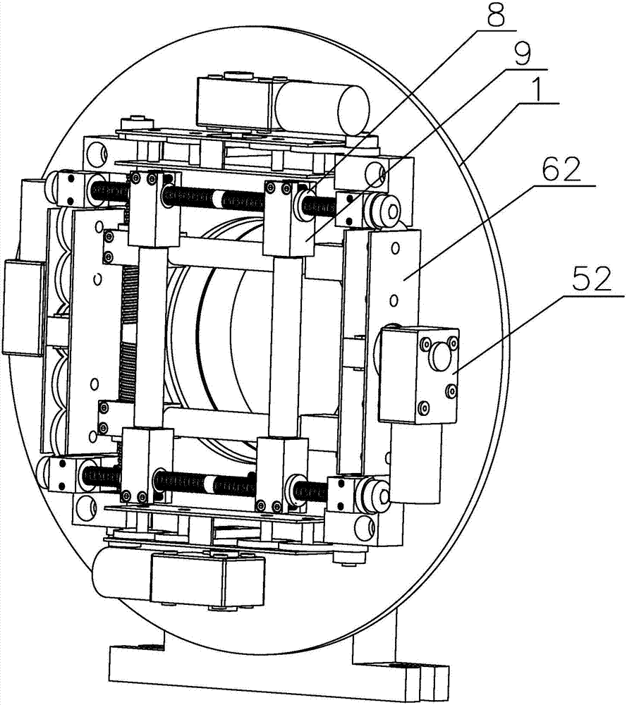
[0038] Such as Figure 1-4 As shown, it is the best embodiment of the present invention, a clawless pipe clamping chuck, including a motherboard 1, and a through hole 2 is provided in the middle of the motherboard 1 to allow pipe fittings to pass through. The pipe is a clawless fixture that enables the pipe to slide axially along the center of the motherboard 1 in the through hole 2 .

[0039] The clawless fixture includes at least two pairs of clamping rods and a clawless driving mechanism for controlling the movement of each pair of clamping rods toward or against each other. The driving mechanism is installed on the motherboard 1, and each pair of clamping...


PUM


Abstract

The invention relates to the technical field of pipe clamps, in particular to a claw-free chuck for clamping pipes. A through hole accepting penetration of the pipes is formed in the middle of a main plate, and the main plate is provided with a claw-free clamp capable of clamping the pipes and enabling the pipes to slide in the through hole in the axial direction of the center of the main plate. According to the claw-free chuck for clamping the pipes, claws and clamping bases pushing the claws are eliminated, and therefore the thickness of the claw-free chuck for clamping the pipes is reduced, the self weight of the chuck is lowered, and feeding waste of the pipes is reduced; because the claws are eliminated, the problem that claw handles extend out of the maximum diameter part of the chuck (namely the main plate) is avoided, the installation space of the chuck is greatly reduced, the manufacturing cost of the chuck is greatly reduced, and the stability is high; pipe loads are retained by screw rods firstly, worm motors just need to bear small retaining force, and gearboxes of the worm motors are protected against damage caused by overload due to the two-stage retaining function. In addition, the claw-free chuck is simple in structure, small in size and light in self weight and has full stroke.

Description

technical field [0001] The invention relates to the technical field of pipe fixtures, in particular to a clawless pipe chuck. Background technique [0002] The principle of pipe cutting machine and pipe welding machine is through the mutual cooperation of computer and hydraulic pressure, and the electric system controls the oil circuit movement direction of the hydraulic system, and pushes the carriage to make linear reciprocating motion. The microcomputer will walk according to the user-edited cutting route. During the reciprocating movement, the signal detected by the carriage limit is used as a basis to control and change the movement of its oil circuit, so as to achieve the expected cutting route. [0003] Pipe cutting machines, pipe welding machines, etc. need to fix the pipe fittings before work. Generally, chucks are used to fix the pipe fittings. The pipe fittings are clamped by the claws on the chuck. The chuck with claws has a complex structure and the overall thic...

Claims


Application Information

Patent Timeline
Patent Type & Authority Patents(China)
IPC IPC(8): B23Q3/08B23K37/053B23B31/10
CPCB23B31/10B23K37/0533B23K2101/06
Inventor 俞雪清
Owner 常州市力源恒机械有限公司
Why Eureka
Try Eureka