Rear-arranged rear-drive type three connection rod rear suspension frame rear axle structure for motor

A three-link, rear suspension technology, applied in the direction of suspension, elastic suspension, cantilever mounted on the pivot, etc., can solve the problems of unsatisfactory rear axle structure, complex structure, etc., to meet the requirements of force transmission and Strength requirements, the effect of improving strength

Active Publication Date: 2013-08-07
SUZHOU AUTO TECH
View PDF6 Cites 10 Cited by
  • Summary
  • Abstract
  • Description
  • Claims
  • Application Information

AI Technical Summary

Problems solved by technology

Under the general trend of electric vehicle development, the vast majority of electric vehicle manufacturers just replace the engine with a motor to provide power, and continue to use the traditional vehicle transmission system (drive shaft, main transmission, differential, etc.), combining the two Mechanically combined, the structure is relatively complicated, and the rear axle structure used in it cannot meet the needs of the electric vehicle motor rear-mounted rear-drive motor, drive shaft, and elastic elements above the rear axle on the non-load-bearing body (with frame) Spatial layout requires the layout and optimization of traditional rear axles and similar curved tube beam rear axle structures

Method used


Image

  • Rear-arranged rear-drive type three connection rod rear suspension frame rear axle structure for motor
  • Rear-arranged rear-drive type three connection rod rear suspension frame rear axle structure for motor
  • Rear-arranged rear-drive type three connection rod rear suspension frame rear axle structure for motor

Examples


Embodiment Construction

[0012] The present invention will be described in detail below with regard to specific accompanying drawings.

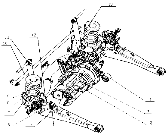
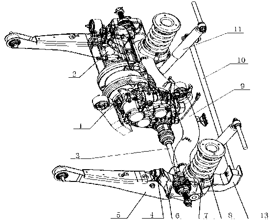
[0013] Such as figure 1 with figure 2 Shown is a motor rear drive type three-link rear suspension rear axle structure, including a shaft joint 6, a motor 2, a transmission 1, a drive shaft 3, a shock absorber 11, a pipe beam 9, a lower longitudinal arm 5 and a thrust Rod 10; the output shaft of the motor 2 is connected to the input end of the transmission 1, the output end of the transmission is connected to the drive shaft 3 arranged horizontally, and the two ends of the drive shaft are connected in series to the shaft joint 6 through gears, the shaft One side of the joint is fastened to the lower longitudinal arm 5 through the connecting bracket 4, and a hole is opened at the lower left corner of the other side of the shaft joint 6; The position protrudes backward, and the protruding part of the pipe beam can avoid the mutual interference between the pipe be...


PUM


Abstract

The invention relates to a rear-arranged rear-drive type three connection rod rear suspension frame rear axle structure for a motor. The structure comprises pivot journals, a motor, a speed changer, a driving shaft, a shock absorber, a pipe beam, a lower vertical arm and a push force rod. The pipe beam is 'n'-shaped, the middle portion of the pipe beam protrudes backwards, and a push force rod support and a single support are connected at the positions of the pipe beam close to the left end and the right end respectively in a welding mode. A semicircular groove recessed downwards is respectively arranged at one end of the push force rod support and the single support, and two ends of the pipe beam are embedded in the semicircular grooves in a welding mode. A spring seat is respectively arranged at one end of the push force support and the single support. The push force rod support is formed by welding two metal plates in a splicing mode, and the spring seats are arranged backward in a deviated mode relative to the axis position of the pipe beam. By means of arrangement and optimization of a traditional back axle and a similar bending pipe beam back axle structure, space arrangement requirements of the motor, the driving shaft and elastic elements can be met, and the requirements for stress transfer and strength can be met.

Description

technical field [0001] The invention belongs to the field of an automobile chassis rear axle assembly, and in particular relates to a motor rear-mounted rear-drive type three-link rear suspension rear axle structure. Background technique [0002] In the existing market, both traditional automobile axles and traditional motors have developed relatively maturely. Under the general trend of electric vehicle development, the vast majority of electric vehicle manufacturers just replace the engine with a motor to provide power, and continue to use the traditional vehicle transmission system (drive shaft, main transmission, differential, etc.), combining the two Mechanically combined, the structure is relatively complicated, and the rear axle structure used in it cannot meet the needs of the electric vehicle motor rear-mounted rear-drive motor, drive shaft, and elastic elements above the rear axle on the non-load-bearing body (with frame) Spatial arrangement requires the arran...

Claims


Application Information

Patent Timeline
Patent Type & Authority Applications(China)
IPC IPC(8): B60B35/14B60G7/00B60G11/14
Inventor 宿佳敏张广锋高立军李宏声田永义李明
Owner SUZHOU AUTO TECH
Why Eureka
Try Eureka