Five-drive spherical robot using mixed synchronous belt
A spherical robot and synchronous belt technology, applied in motor vehicles, transportation and packaging, etc., can solve problems such as large torque, complex structure, difficult to drive, etc.
- Summary
- Abstract
- Description
- Claims
- Application Information
AI Technical Summary
Problems solved by technology
Method used
Image
Examples
Embodiment 1
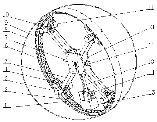
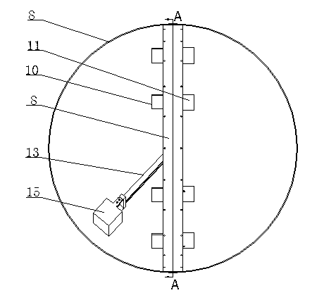
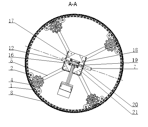
[0027] see Figure 1~Figure 11 , a spherical robot driven by a hybrid synchronous belt, comprising a spherical shell 8 and a track frame 6, the spherical shell is fixed on the threaded hole 602 on the outer surface of the track frame with threads, and the inner surface of the track frame 6 has two tracks 603, two tracks A circular rigid belt composed of a hybrid synchronous belt 9 is fixed between them, and the holes 601 and 901 are fixedly connected. The hole 2105 in the central outer frame 21 is fixedly connected with the hole 1702 of the central inner frame 17 by bolts. A pair of bearing housings 18 are installed on both sides of the central inner frame 17 and are fixed through holes 1701. A central shaft 20 is fitted between the two bearing housings, and the central shaft 20 is axially fixed. One end of the two ends of the shaft is connected to the central axis motor 7 through a coupling 19, and the other end is connected to the electromagnetic clutch brake 12 through a c...
Embodiment 2
[0029] The technical solution of this embodiment is basically the same as that of Embodiment 1, especially in that:
[0030] In this example, participating in figure 1 , Image 6 with Figure 9 , the hybrid synchronous belt 9 is made up of a metal belt layer 902 and a noise-proof layer 903, the metal belt layer has high strength and high flexibility, and the noise-proof layer is coated with anti-noise and anti-friction plastics on the metal surface to reduce vibration during movement. The hybrid synchronous belt is fixed on the threaded hole 601 of the track frame 6 through the hole 901 to form an annular synchronous belt, and the synchronous belt pulley 4 moves on the hybrid synchronous belt 9 .
Embodiment 3
[0032] The technical solution of this embodiment is basically the same as that of Embodiment 1, especially in that:
[0033] In this example, see figure 1 with Image 6 , the T-shaped support arm 5 is a thin metal plate, and the structural diagram is as follows Image 6As shown, the hole 501 and the hole 2103 of the center outer frame 21 are fixed with bolts, and the two holes 503 at the other end are fixed with the pinch roller shaft 2, and the track pinch wheel 1 is installed on the pinch wheel shaft 2, and the flange 505 is used to fix the bearing seat . The circumferential motor 3 is fixed on the flange 504, and the 3 shafts of the circumferential motor are connected to the shaft of the synchronous pulley through a coupling, thereby driving the synchronous pulley to rotate. A pair of T-shaped support arms fixes the battery box 11 on the flange 504 on the other support arm, and the battery box is installed with a battery to provide power to the motor and to balance the w...
PUM
 Abstract
Description
Claims
Application Information
 - R&D
- Intellectual Property
- Life Sciences
- Materials
- Tech Scout
- Unparalleled Data Quality
- Higher Quality Content
- 60% Fewer Hallucinations
Browse by: Latest US Patents, China's latest patents, Technical Efficacy Thesaurus, Application Domain, Technology Topic, Popular Technical Reports.
© 2025 PatSnap. All rights reserved.Legal|Privacy policy|Modern Slavery Act Transparency Statement|Sitemap|About US| Contact US: help@patsnap.com


