High-voltage direct-current grounding electrode line high-resistance fault positioning method

A technology of high-voltage direct current and positioning method, which is applied in the direction of fault location, information technology support system, etc., and can solve problems such as low voltage level of grounding electrode line, low reliability and accuracy of distance measurement, and great influence on safe operation of DC system

Active Publication Date: 2013-08-07
KUNMING UNIV OF SCI & TECH +1
View PDF7 Cites 20 Cited by
  • Summary
  • Abstract
  • Description
  • Claims
  • Application Information

AI Technical Summary

Problems solved by technology

[0003] The voltage level of the ground electrode line is low, and the probability of line failure is relatively high. After the ground electrode line fails, it will affect the DC bipolar system, which not only has a great impact on the safe operation of the DC system, but also has a great impact on the stable operation of the backbone grid of the power grid.
At present, most grounding electrode lines are equipped with pulse traveling wave ranging devices, but the reliability and accuracy of ranging are not high. When the grounding electrode line is faulty, it often happens that the distance cannot be measured.

Method used


Image

  • High-voltage direct-current grounding electrode line high-resistance fault positioning method
  • High-voltage direct-current grounding electrode line high-resistance fault positioning method
  • High-voltage direct-current grounding electrode line high-resistance fault positioning method

Examples


Embodiment 1

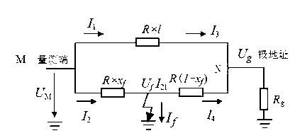
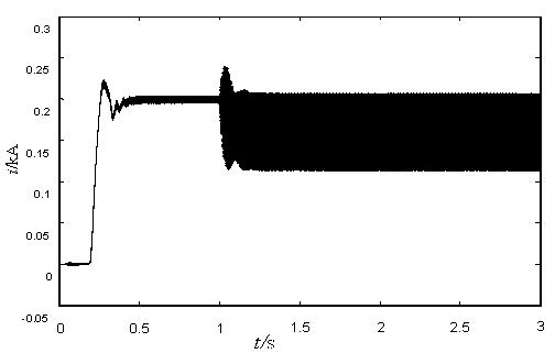
[0037] Example 1: 800kV DC ground electrode line such as figure 1 shown. The line parameters are as follows: the total length of the line is 80km, the line impedance is: 0.00756+j0.39999Ω / km, and the pole address resistance is 0.2Ω. The data sampling rate is 6.4kHz. Ground electrode line l 2 A ground fault occurs 50km away from the measurement end, and the transition resistance is 0.2Ω.

[0038] Measured ground electrode line l 2Measuring terminal current when ground fault occurs i 1 and i 2 like figure 2 , 3 shown, measure the terminal voltage u M like Figure 4 shown.

[0039] According to the specific steps of the fault location method in the foregoing summary of the invention, the fault location data is calculated as follows: Figure 5 shown. According to the obtained fault location data, the fault distance can be obtained x f =50.4km.

Embodiment 2

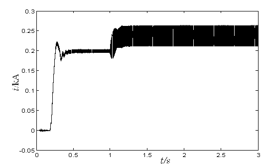
[0040] Example 2: 800kV DC ground electrode line such as figure 1 shown. The line parameters are as follows: the total length of the line is 80km, the line impedance is: 0.00756+j0.39999Ω / km, and the pole address resistance is 0.2Ω. The data sampling rate is 6.4kHz. Ground electrode line l 2 A ground fault occurs 50km away from the measuring end, and the transition resistance is 2Ω.

[0041] Measured ground electrode line l 2 Measuring terminal current when ground fault occurs i 1 and i 2 like Image 6 , 7 shown, measure the terminal voltage u M like Figure 8 shown.

[0042] According to the specific steps of the fault location method in the foregoing summary of the invention, the fault location data is calculated as follows: Figure 9 shown. According to the obtained fault location data, the fault distance can be obtained x f =50.3km.


PUM

PropertyMeasurementUnit
Transition resistanceaaaaaaaaaa

Abstract

The invention provides a high-voltage direct-current grounding electrode line high-resistance fault positioning method and belongs to the technical filed of power system protection and ranging. When grounding faults occur in a high-voltage direct-current grounding electrode, terminal voltage and current are measured by utilizing a normal line to calculate voltage to a electrode stop point, terminal voltage, current and fault boundary conditions are measured by utilizing a fault line to calculate voltage of the electrode stop point, a fault positioning function is written according to electrode stop point voltage equivalence, and fault distance is calculated by solving the fault positioning function. By the method, fault grounding electrode line fault ranging is achieved based on existing fault recording data, measurable single-end voltage and current are utilized, opposite-end data is unnecessary, high sampling rate is unnecessary, and filed implementation is easy.

Description

technical field [0001] The invention relates to the technical field of power system protection and ranging, in particular to a method for locating high-resistance faults of high-voltage direct current grounding pole lines. Background technique [0002] The grounding electrode line is an indispensable part of the DC transmission system. The DC system converter station is generally tens to more than 100 kilometers away from the grounding point, and the grounding electrode lead with two conductors in parallel is usually erected. [0003] The voltage level of the grounding pole line is low, and the probability of line failure is high. After the grounding pole line fails, it will affect the DC bipolar system, which not only has a great impact on the safe operation of the DC system, but also has a great impact on the stable operation of the grid backbone. At present, most of the grounding pole lines are equipped with pulse traveling wave ranging devices, but the reliability and ac...

Claims


Application Information

Patent Timeline
IPC IPC(8): G01R31/08
CPCY04S10/522Y04S10/52
Inventor 束洪春龙丹
Owner KUNMING UNIV OF SCI & TECH
Why Eureka
Try Eureka