Four-pole bearingless switched reluctance motor

A switched reluctance motor, bearingless technology, applied in the direction of electrical components, magnetic attraction or thrust holding device, etc., can solve the problems of low fault tolerance and reliability, low winding utilization rate, low slot full rate, etc., to achieve Good for heat dissipation, small moment of inertia, and small mutual inductance

Active Publication Date: 2013-08-07
SOUTHEAST UNIV
View PDF3 Cites 1 Cited by
  • Summary
  • Abstract
  • Description
  • Claims
  • Application Information

AI Technical Summary

Problems solved by technology

The bearingless switched reluctance motor using this method has a complex structure, low slot fullness, low winding utilization, and the torque winding and the suspension force winding are nested on the same stator tooth, the magnetic circuit is almost identical, and the coupling is serious , low fault tolerance and reliability

Method used


Image

  • Four-pole bearingless switched reluctance motor
  • Four-pole bearingless switched reluctance motor

Examples


Embodiment Construction

[0030] The technical solution of the present invention will be described in detail below in conjunction with the accompanying drawings.

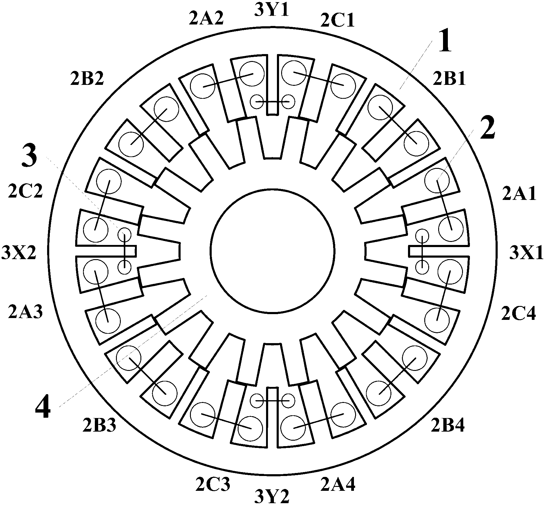
[0031] The four-pole bearingless switched reluctance motor of the present invention includes a stator 1 and a rotor 4 . The stator 1 is provided with an even number of stator teeth, which are evenly distributed, and stator slots are formed between adjacent stator teeth, and each stator tooth has another stator tooth opposite to it in the radial direction. The stator teeth can be divided into two groups with the same number, called main teeth and auxiliary teeth, which are arranged at intervals, that is, one of the two adjacent stator teeth is the main tooth and the other is the auxiliary tooth. There are concentrated windings on the stator teeth, which include torque windings 2 for outputting mechanical energy and suspension force windings 3 for suspending the rotor. The number of torque winding coils is equal to the number of main teeth of ...


PUM


Abstract

The invention discloses a four-pole bearingless switched reluctance motor. An even number of salient pole teeth are arranged on a stator and can be divided into main teeth and secondary teeth according to different functions; two kinds of different windings are nested on the stator teeth; torque windings are used for outputting mechanical torque and are sequentially nested on all the main teeth of the motor; and four phases of levitation force windings are available and are nested on four secondary teeth at vertical orthogonal positions of the motor for controlling the displacements of the motor rotor in the horizontal X axis direction and the vertical Y axis direction respectively. According to the motor, the advantage of simple and firm structure of the switched reluctance motor is kept, the full rate of each motor winding slot is high, and the reliability is good; each motor torque winding is of a half-tooth winding structure, and different phases of windings are not placed in the same stator slot, so that the electric, magnetic and thermal coupling among the phases are obviously weakened, and the fault tolerance is improved; and meanwhile, bearingless operation of the switched reluctance motor is realized through skillful change of the winding mode, so that the switched reluctance motor can bring the advantage of suitability for high speed and ultra-high speed work into play.

Description

technical field [0001] The invention belongs to the technical field of motor manufacturing and application, and relates to a novel bearingless switched reluctance motor. Background technique [0002] The manufacturing cost and maintenance cost of permanent magnet motors using rare earth permanent magnet materials are relatively high, and due to the use of permanent magnets, the reliability and temperature limit of the motor are significantly reduced. Especially in recent years, the price of rare earth permanent magnet materials fluctuates violently, which limits the large-scale promotion of this type of motor. At the same time, switched reluctance motor drive systems without permanent magnets are gaining more and more attention. The switched reluctance motor has a double salient pole structure. The stator and rotor are made of ordinary silicon steel sheets laminated. There is neither permanent magnet nor winding on the rotor. There is only concentrated winding on the stator...

Claims


Application Information

Patent Timeline
Patent Type & Authority Applications(China)
IPC IPC(8): H02N15/00
Inventor 花为华浩鹿泉峰程明
Owner SOUTHEAST UNIV
Why Eureka
Try Eureka