Conical rod piece drive positioning tooling and cylindrical grinding machine

A technology for positioning tooling and rods, which is applied in the direction of grinding machines, machine tools designed for grinding the rotating surface of workpieces, manufacturing tools, etc. It can solve problems such as affecting cylindricity, workpieces and grinding wheels are not perpendicular, workpieces and tops cannot be completely overlapped, etc. To achieve the effect of improving the grinding accuracy

Active Publication Date: 2013-08-14
丹东丰能工业股份有限公司
View PDF10 Cites 8 Cited by
  • Summary
  • Abstract
  • Description
  • Claims
  • Application Information

AI Technical Summary

Problems solved by technology

[0002] The circular drive rod of the cylindrical grinding machine (M13320 cylindrical grinding machine tool) (also called a shift lever or a shift fork, which is installed on the rotating disc (drive wheel) of the headstock) is usually a cylinder, that is, a cylindrical rod , when the cylindrical rod rotates with the spindle box (headstock), it drives the workpiece to run through the collet (one end of the collet is clamped and fixed on the workpiece, the other end is vertica...

Method used


Image

  • Conical rod piece drive positioning tooling and cylindrical grinding machine

Examples


Embodiment Construction

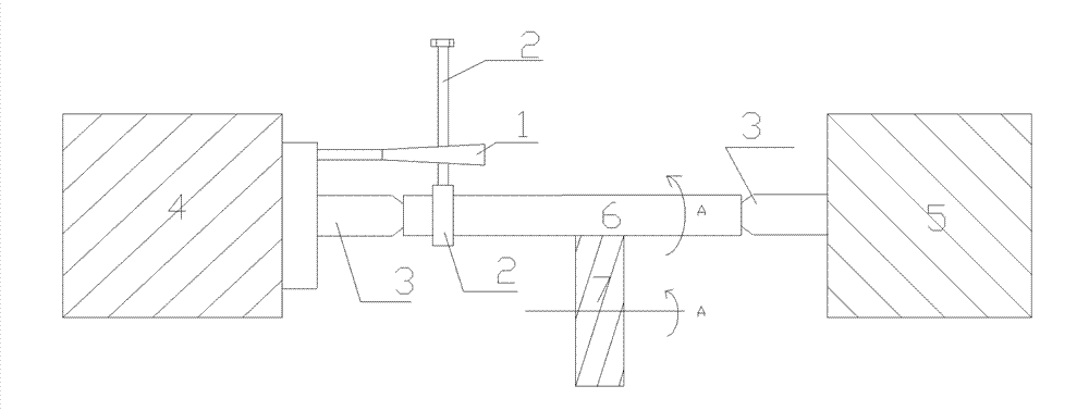
[0015] refer to figure 1 As shown, a conical rod drive positioning tool, such as figure 1 The driving rod 1 in the middle is a rod-shaped structure, one end of which is truncated conical, and the other end is a cylindrical rod, and one end of the cylindrical rod is fixedly connected to the upper bottom surface of the truncated conical rod (the upper surface of the truncated conical rod). The diameter of the bottom surface is smaller than the diameter of the bottom surface), and the cone angle of the truncated cone is 15°±30′.

[0016] refer to figure 1 Shown, a kind of cylindrical grinding machine, comprises the head box that is provided with drive wheel relatively, bed tail box, driving lever (or be referred to as shift fork) 1 and chuck 2, on the head box 4 and the tail box The adjacent surface of 5 is relatively provided with a top 3, the top abuts against the two ends of the cylindrical workpiece 6 to be ground, and the workpiece to be ground is positioned by the top,

...


PUM


Abstract

The invention relates to a cylindrical grinding machine, particularly to a conical rod piece drive positioning tooling, that is, the conical rod piece drive positioning tooling (driving rod) of the cylindrical grinding machine. The conical rod piece drive positioning tooling is in a rod-shaped structure, and a rod body in a cone frustum shape is arranged at one end. The conical rod piece drive positioning tooling is used for driving workpieces of the cylindrical grinding machine to rotate, and the accuracy of the cylindricity of grinded spindly shafts can be improved.

Description

technical field [0001] The invention relates to a cylindrical grinder, in particular to a conical rod driving and positioning tool and a cylindrical grinder. Background technique [0002] The circular drive rod of the cylindrical grinding machine (M13320 cylindrical grinding machine tool) (also called a shift lever or a shift fork, which is installed on the rotating disc (drive wheel) of the headstock) is usually a cylinder, that is, a cylindrical rod , when the cylindrical rod rotates with the spindle box (headstock), it drives the workpiece to run through the collet (one end of the collet is clamped and fixed on the workpiece, the other end is vertically installed, and it is perpendicular to the circular drive rod) to drive the workpiece to run; but in During its operation, due to the instability of the hydraulic pressure of the machine tool, the workpiece and the top cannot be completely overlapped, and the chuck will slightly slide on the cylindrical rod in the direction...

Claims


Application Information

Patent Timeline
IPC IPC(8): B24B5/04B24B5/35
Inventor 徐高太
Owner 丹东丰能工业股份有限公司
Why Eureka
Try Eureka