Fuel tank

A fuel tank and fuel tank technology, which is applied in the layout, power plant, transportation and packaging combined with the fuel supply of the internal combustion engine, can solve the problem of not being able to absorb oil, and achieve the effects of improving service life, easy manufacturing and simple structure

Inactive Publication Date: 2013-08-14
GUANGXI LIUGONG MASCH CO LTD
View PDF6 Cites 13 Cited by
  • Summary
  • Abstract
  • Description
  • Claims
  • Application Information

AI Technical Summary

Problems solved by technology

[0003] The object of the present invention is to provide a fuel tank that can still take oil when the fuel tank is small and the fuel tank is tilted, aiming at the shortcomings of the existing fuel tank that the oil pipe cannot absorb oil when the fuel tank is small and the fuel tank is tilted. To a fuel tank with a high actual utilization rate of fuel and fuel tank volume

Method used


Image

  • Fuel tank
  • Fuel tank
  • Fuel tank

Examples


Embodiment 1

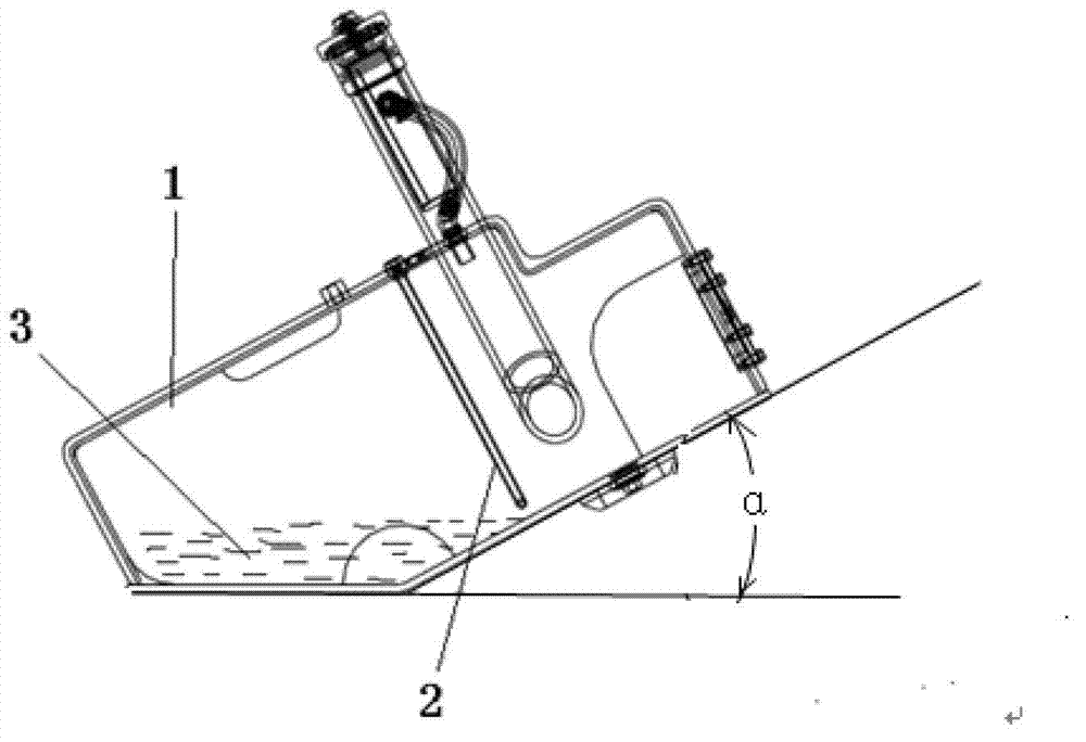
[0021] Figure 2 to Figure 4 A preferred implementation of the present invention is shown, and the implementation of this example can be applied to other construction machinery equipment.

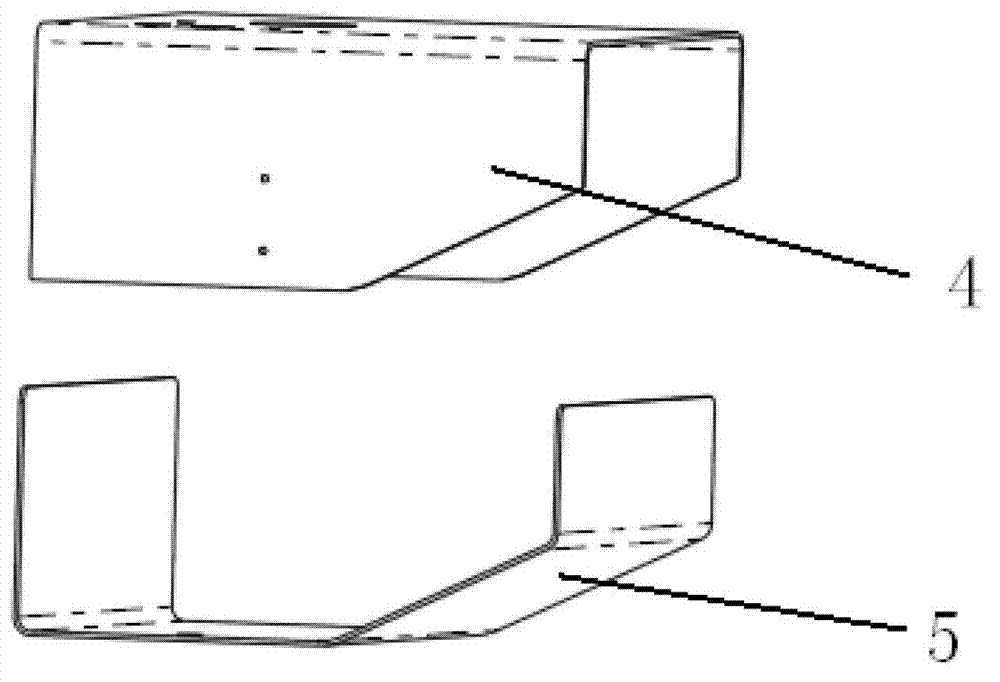
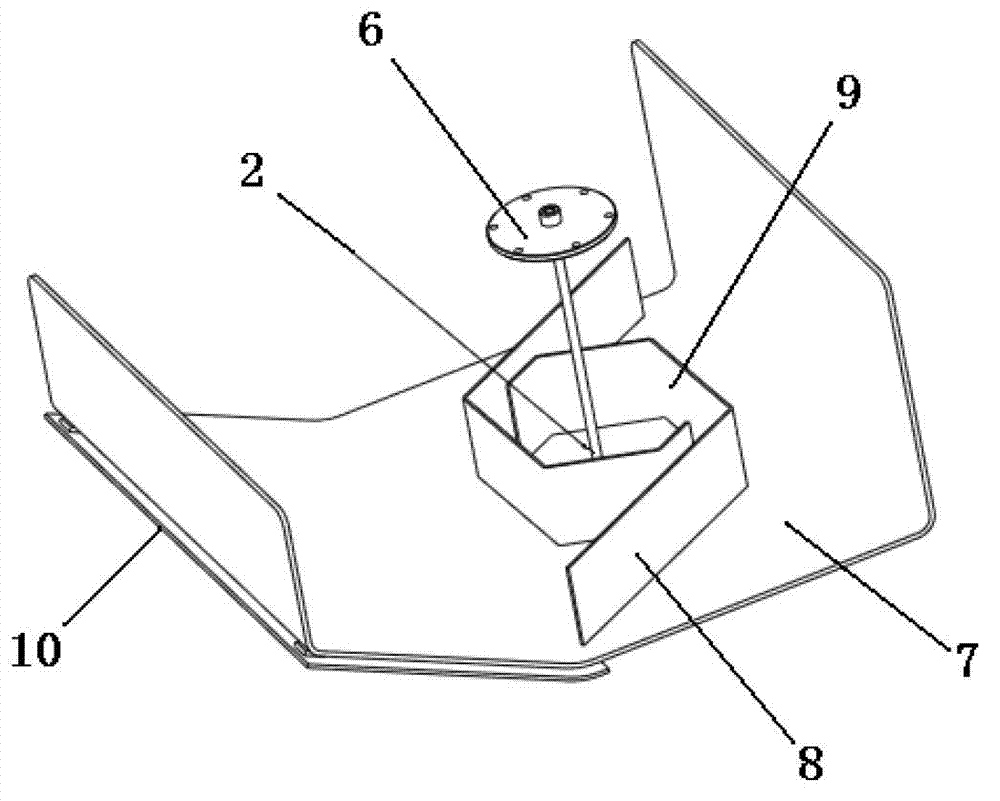
[0022] Such as figure 2 As shown, the tank body 1 of the fuel tank in this embodiment is composed of an upper bent plate 4 and a lower bent plate 5, both of which are U-shaped, and they are interlocked and welded Form a box body, wherein the upper bent plate 4 forms the left side plate, right side plate and top plate of the box body, and the lower bent plate 5 forms the rear side plate, front side plate and bottom plate of the box body. Wherein the rear half of the base plate is upwardly warped, and the outer side of the warped part is fixed with a guard plate 10 by bolts, which can be replaced after the guard plate 10 is bumped, deformed and damaged. Such as image 3 As shown, an oil suction device 6 is installed on the top plate of the box body 1, and the oil suction pipe 2 of the oil...

Embodiment 2

[0024] Such as Figure 5 Image 6 As shown, in this embodiment, the coaming plate 13 forms a vertical mouth-shaped oil collection chamber on the bottom plate 7 of the box body, and a front oil collection inlet 16 is provided in front of the mouth-shaped coaming plate 13. The rear of the font coaming 13 is provided with a rear oil collection inlet 17, and in front of the coaming 13 are provided with two front vertical plates 14 arranged in a figure-of-eight shape to form a figure-of-eight oil collection port with an opening facing forward. There are two parallel inner vertical plates 15 in the cavity to form a long and narrow channel, one end of which is in communication with the front oil collecting inlet 16 of the coaming plate, and the other end extends beyond the oil suction port of the oil suction device in the oil collecting cavity To the rear coaming plate, the long and narrow channel forms an oil collecting channel with the oil collecting port and the front oil collect...


PUM


Abstract

The invention relates to a fuel tank and overcomes defects that a fuel sucking pipe of the existing fuel tank cannot suck fuels when the fuel amount is small and the fuel tank slants. The fuel tank comprises a tank body, wherein a fuel sucking device is arranged in the tank body, and a vertically upward coaming is arranged on a base board disposed in the tank body and encloses a fuel collection accommodating cavity on the base plate of the tank body surrounding a fuel sucking port of the fuel sucking device. A fuel collection channel attached to the base plate of the tank body and connecting the inside and the outside of the fuel collection accommodating cavity is arranged on the coaming in the horizontal direction, and two ends of the fuel collection channel are respectively located in the front of and at the back of the fuel sucking port. When the fuel tank slants back and forth, the fuels on the periphery of the coaming can be collected into the fuel collection accommodating cavity through the fuel collection channel, the fuels entering the fuel collection accommodating cavity cannot flow out of the fuel collection accommodating cavity along with slanting of the fuel tank, therefore the fuel sucking port is ensured to be soaked into the fuels and suck the fuels at any time, residual fuels in a diesel tank can be used maximally, and the practical use ratio of the fuel tank volume is improved.

Description

technical field [0001] The invention relates to a fuel tank, in particular to a fuel tank with high volume utilization rate used on construction machinery equipment. Background technique [0002] Most construction machinery equipment is driven by an internal combustion engine, so such machinery equipment is equipped with a fuel tank for storing fuel, and oil is taken from the fuel tank through an oil suction device to supply fuel to the engine. Such as figure 1 As shown, in the existing fuel tank, the oil intake end of the oil suction pipe 2 is fixed at a certain position at the bottom of the fuel tank body 1, and this fuel tank will not have the oil suction pipe that cannot get the oil when the fuel is sufficient. problem, but when there is less fuel 3 in the fuel tank and the machine equipment is on the ramp, the fuel tank body 1 will tilt forward and backward along with the machine equipment, such as figure 1 As shown, the fuel oil 3 positioned at the bottom of the fuel...

Claims


Application Information

Patent Timeline
Patent Type & Authority Applications(China)
IPC IPC(8): B60K15/077
Inventor 张碧荣王涛唐磊许明疆廖玉懂张永深
Owner GUANGXI LIUGONG MASCH CO LTD
Why Eureka
Try Eureka